Wearable device for visual assisting
A wearable device and visual technology, which is applied in the direction of eye testing equipment, application, medical science, etc., can solve the problems of insufficient excitability of visual cortex cells, inability to effectively train weak eyes, and failure to follow the training intensity, so as to alleviate the deterioration of vision , avoiding the intensification of visual differentiation, and the effect of strong ease of use
- Summary
- Abstract
- Description
- Claims
- Application Information
AI Technical Summary
Problems solved by technology
Method used
Image
Examples
Embodiment 1
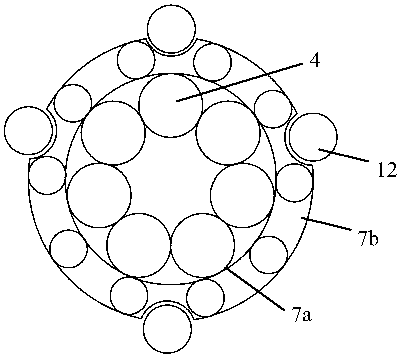
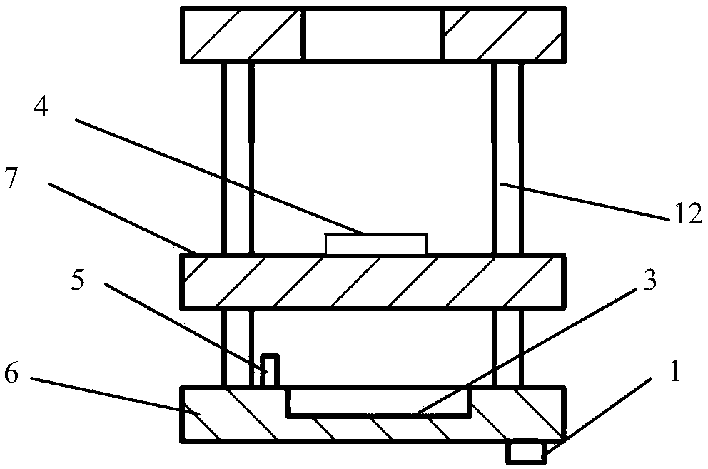
[0034] figure 1 A schematic structural diagram of a visual aid wearable device is shown, such as figure 1As shown, the visual aid wearable device at least includes an environment monitoring module 1 , a central processing module 2 , a display module 3 , a lens 4 , an eye state evaluation module 5 and a housing 6 . The environment monitoring module 1 , the central processing module 2 , the display module 3 , the lens 4 and the eye state assessment module 5 are all fixed on the casing 6 . Both the environmental monitoring module 1 and the eye state assessment module 5 are communicatively coupled to the central processing module 2 to transmit the collected data to the central processing module 2 for processing and generate control signals for controlling the display module 3 and the lens 4 . The environment monitoring module 1 can be used to collect image data of the surrounding environment and transmit it to the display module 3 in real time for display. The environment monito...
Embodiment 2
[0050] This embodiment is a further improvement on Embodiment 1, and repeated content will not be repeated here.
[0051] Preferably, the display module can be configured to have several working modes with different working states. One or more display modules 3 display the display content to the user in a way corresponding to the left eye and the right eye respectively, and when the wearable device for visual assistance displays content for the left eye and the right eye simultaneously through a display module, the display Different parts of the module make up the display area for the left and right eyes. For example, a dividing component is provided between the display module and the lens to divide the lens and the display module into two parts that do not interfere with each other, that is, the left eye cannot see the display content in the right display module through the left lens. The visual content displayed to the user may be a panoramic image collected in real time by...
Embodiment 3
[0059] This embodiment is a further improvement on the aforementioned Embodiment 1 and Embodiment 2, and the repeated content will not be repeated.
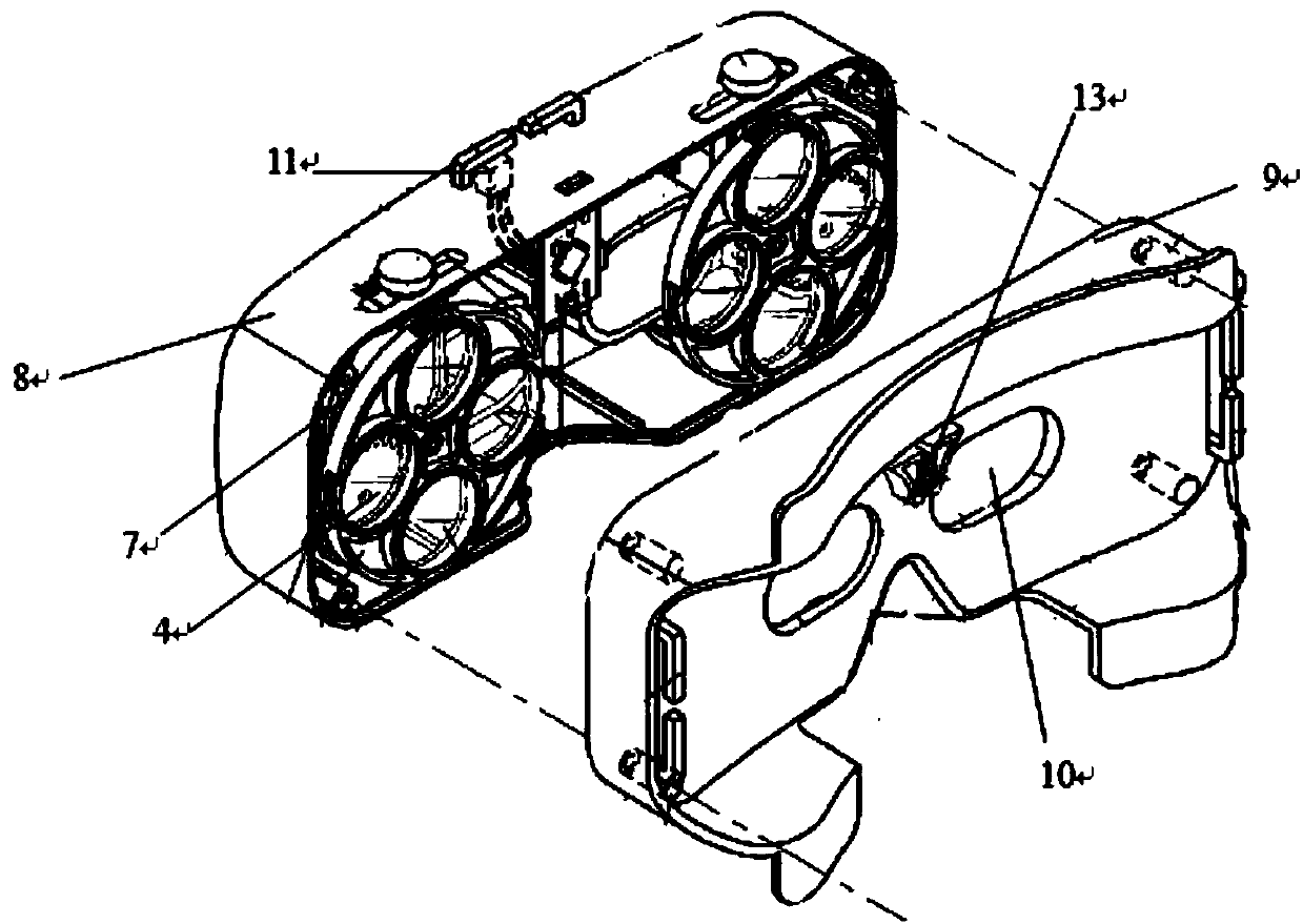
[0060] The invention also discloses a preferred wearable device for visual aid, which can be conveniently used by wearing it. Such as image 3 As shown, the wearable device includes a first outer frame 8 and a second outer frame 9 . The shape of the first outer frame 8 is defined by a hollow rectangular parallelepiped with one surface open, wherein the wearable device for visual aid can be fixed in a manner of being integrally embedded in the hollow cavity of the first outer frame. The shape of the second outer frame 9 is defined by a hollow cuboid with one face open, wherein the section curve of the open end face of the second outer frame is consistent with the skin curve at the eye position, or the opening of the second outer frame A sealing ring is fixed on the shaped end surface in a bonding manner, so that when the user we...
PUM
 Abstract
Description
Claims
Application Information
 - R&D
- Intellectual Property
- Life Sciences
- Materials
- Tech Scout
- Unparalleled Data Quality
- Higher Quality Content
- 60% Fewer Hallucinations
Browse by: Latest US Patents, China's latest patents, Technical Efficacy Thesaurus, Application Domain, Technology Topic, Popular Technical Reports.
© 2025 PatSnap. All rights reserved.Legal|Privacy policy|Modern Slavery Act Transparency Statement|Sitemap|About US| Contact US: help@patsnap.com


