
Punching die capable of automatically leveling and machining inclined plane and machining method thereof

A punching and bevel technology, which is applied to punching dies for automatically leveling and machining bevels and their processing fields, can solve the problems of reduced workpiece quality, large punching strokes, and inability to increase punching speed.

Pending Publication Date: 2019-12-03
深圳数码模汽车技术有限公司
View PDF0 Cites 1 Cited by
  • Summary
  • Abstract
  • Description
  • Claims
  • Application Information

AI Technical Summary

Problems solved by technology

[0002] In the car seat frame series parts, because the shape and surface of the seat basin parts are irregular, and there are many locking and positioning holes in the whole part, punch holes on many slopes or special-shaped surfaces, and punch holes on the normal side It is necessary to use the inclined wedge to swing out the corresponding angle for punching. When the angled punching is used, when the gap between the inclined wedge and the die is not in place, it will lead to large punching holes, the edge of the lower die is easy to be damaged, and there is no need to align the workpiece for punching. The structure design of the hole die is complicated, and the punching speed of the die PPM cannot be increased, etc., which leads to low production efficiency and a decline in the quality of the workpiece, etc.

Method used


Image

  • Punching die capable of automatically leveling and machining inclined plane and machining method thereof
  • Punching die capable of automatically leveling and machining inclined plane and machining method thereof
  • Punching die capable of automatically leveling and machining inclined plane and machining method thereof

Examples


Embodiment Construction

[0028] In order to make the purpose, technical solutions and advantages of the embodiments of the present invention clearer, a clear and complete description will be made below in conjunction with the technical solutions in the embodiments of the present invention. Obviously, the described embodiments are part of the embodiments of the present invention, and Not all examples. Based on the embodiments of the present invention, all other embodiments obtained by persons of ordinary skill in the art without making creative efforts belong to the protection scope of the present invention.

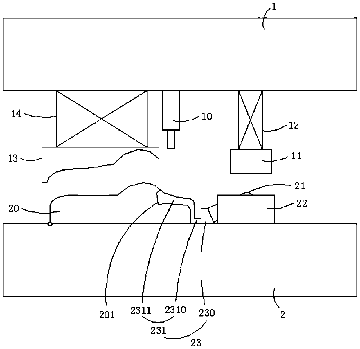
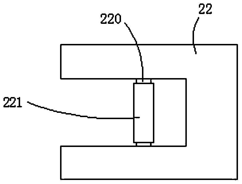
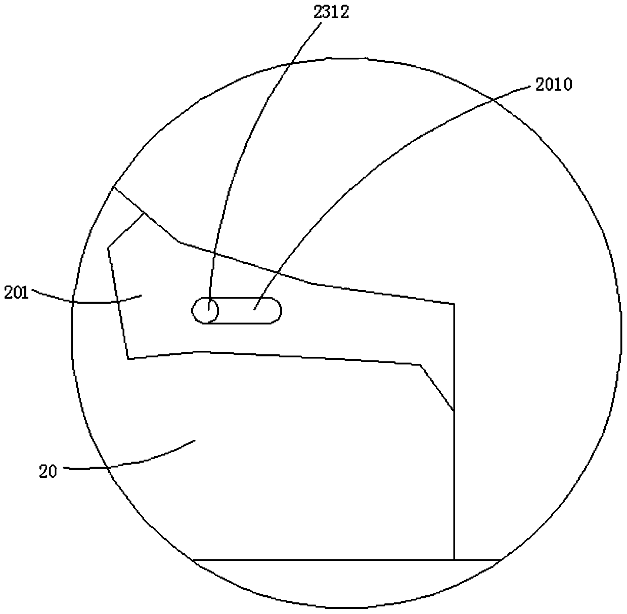
[0029] The punching die of the automatic balance processing inclined-plane of preferred embodiment of the present invention, as figure 1 shown, see also Figure 2-5 , including an upper mold 1 and a lower mold; the lower mold is provided with a lower template 2, and the lower template 2 is provided with a profiling positioning block 20, and the lower part of the profiling positioning block 20 aw...


PUM


Abstract

The invention relates to a punching die capable of automatically leveling and machining an inclined plane. The punching die comprises an upper die and a lower die, a lower die plate is arranged on thelower die, and a profiling positioning block is arranged on the lower die plate; the lower portion of the end, deviating from the side surface to be punched, of the profiling positioning block is hinged to the lower die plate, a rotating arm and a mounting base are arranged on the lower die plate, and the rotating arm is located at one side of the to-be-punched side surface of the profiling positioning block; a top plate is arranged at one end of the rotating arm, a punching female die is arranged on the profiling positioning block, and a punching punch and an upper reverse ejection column are arranged on the upper die; the upper reverse ejection column is connected with the upper die through a first elastic assembly, and a profiling pressure plate is also arranged on the upper die and isconnected with the upper die through a second elastic assembly. According to the present invention, by overturning to flat the punching position and then punching, a conventional wedge structure is replaced, the die has the advantages that a knife edge is not easily damaged, the punching burrs are few, and the precision requirement is low and the like and enables the workpiece quality to be improved, the additional power is not needed for assisting turnover during the turnover process, and the die is simple in structure and low in cost.

Description

technical field [0001] The invention relates to the technical field, and more specifically relates to a punching die for automatically leveling a processing inclined surface and a processing method thereof. Background technique [0002] In the car seat frame series parts, because the shape and surface of the seat basin parts are irregular, and there are many locking and positioning holes in the whole part, punch holes on many slopes or special-shaped surfaces, and punch holes on the normal side It is necessary to use the inclined wedge to swing out the corresponding angle for punching. When the angled punching is used, when the gap between the inclined wedge and the die is not in place, it will lead to large punching holes, the edge of the lower die is easy to be damaged, and there is no need to align the workpiece for punching. The structure design of the hole die is complex, and the punching speed of the die PPM cannot be increased, which leads to low production efficiency...

Claims


Application Information

Patent Timeline
IPC IPC(8): B21D28/34B21D43/00
CPCB21D28/34B21D43/003
Inventor 吴艺谢茂春李愉愉欧任洪
Owner 深圳数码模汽车技术有限公司
Learn More