Knife sharpening assembly of knife sharpener

A knife sharpening machine and component technology, applied in the direction of grinding machines, grinding/polishing equipment, grinding/polishing safety devices, etc., can solve problems such as mechanical grinding that cannot be automated

Inactive Publication Date: 2019-12-03
成都零柒叁科技有限公司
View PDF11 Cites 7 Cited by
  • Summary
  • Abstract
  • Description
  • Claims
  • Application Information

AI Technical Summary

Problems solved by technology

[0003] The purpose of the present invention is to provide a sharpening assembly for a sharpening machine, which s

Method used


Image

  • Knife sharpening assembly of knife sharpener
  • Knife sharpening assembly of knife sharpener
  • Knife sharpening assembly of knife sharpener

Examples


Embodiment 1

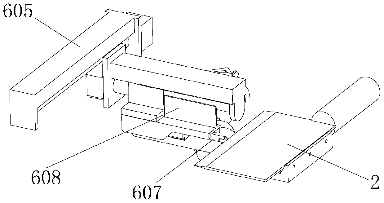
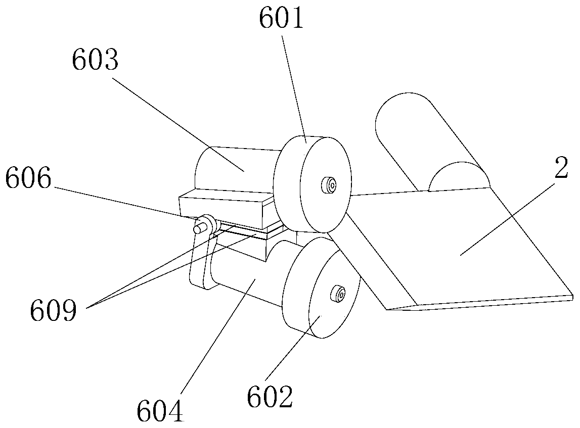
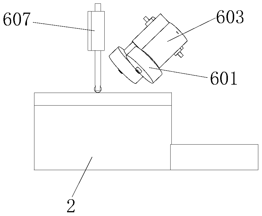
[0029] Such as figure 1 and figure 2 As shown, a sharpening assembly of a knife grinder is installed in the body of the knife sharpener, and is characterized in that it includes an upper grinding wheel 601, a lower grinding wheel 602, an upper grinding wheel motor 603, a lower grinding wheel motor 604, and a grinding wheel walking device 605. The grinding wheel travels The fixed end of the device 605 is installed in the body of the sharpener, and the movable end of the grinding wheel walking device 605 is equipped with a grinding wheel torsion fixing seat 606, which is divided into an upper torsion seat and a lower torsion seat, an upper torsion seat and a lower torsion seat The upper grinding wheel motor 603 is installed on the upper torsion seat, the lower grinding wheel motor 604 is installed on the lower torsion seat, the upper grinding wheel 601 is installed on the rotating shaft of the upper grinding wheel motor 603, and the lower grinding wheel 602 is installed on the ...

Embodiment 2

[0032] The difference between this embodiment and Embodiment 1 is mainly that the shrinking device 609 is a magnet. In this embodiment, magnets are used as the shrinking device 609, which can achieve very special effects. The traditional shrinking device is generally realized by using springs and other devices, but the spring has a fatal shortcoming. The larger the spacing, the greater the force, and the smaller the spacing, the smaller the force. After testing, it is not suitable for use on the grinding wheel. Therefore adopt magnet, when the blade of cutter 2 is thicker, then the tight pressure between upper emery wheel 601 and lower emery wheel 602 during grinding becomes smaller because the distance between magnets is far away, and light force grinding is carried out; when the blade of cutter 2 is thinner , then the pressing force between the upper emery wheel 601 and the lower emery wheel 602 becomes larger due to the close distance between the magnets during grinding, so...

Embodiment 3

[0034] The difference between this embodiment and the previous embodiment is that there are two magnets, which are respectively installed on the sides of the upper torsion seat and the lower torsion seat that are close to each other.


PUM


Abstract

The invention discloses a knife sharpener, in particular to a knife sharpening assembly of the knife sharpener. The knife sharpening assembly is installed in a knife sharpener body and comprises an upper grinding wheel (601), a lower grinding wheel (602), an upper grinding wheel motor (603), a lower grinding wheel motor (604) and a grinding wheel walking device (605), and a contracting device (609) enabling the upper grinding wheel (601) and the lower grinding wheel (602) to get close to each other is arranged between an upper twisting base and a lower twisting base. According to the invention, the distance between the upper grinding wheel and the lower grinding wheel can be automatically adjusted according to the thickness of the knife edge of the knife so as to adapt to different knives,so that the knife sharpener can be suitable for most household knives, and the current situation that a household knife grinder is poor in universality is solved.

Description

technical field [0001] The invention relates to a knife sharpener, in particular to a sharpening assembly of the knife sharpener. Background technique [0002] Knife sharpening is divided into industrial knife sharpening and household knife sharpening. Due to the uniform system of industrial knives, the cause and degree of wear during use are traceable, and the sharpening methods and sharpening equipment are also relatively uniform. Knives, since there is no standard industry stipulating their specifications, the knives produced by each tool manufacturer also have their own characteristics, with different shapes, and the causes of wear vary widely due to users' usage habits, usage environment and other factors. It is difficult to find an effective mechanical automatic grinding method in the position, and the traditional manual grinding method is still used to grind back and forth on the whetstone. Contents of the invention [0003] The object of the present invention is t...

Claims


Application Information

Patent Timeline
IPC IPC(8): B24B3/00B24B27/00B24B55/00
CPCB24B3/00B24B27/0076B24B55/00
Inventor 李凯温元浩朱俊杰
Owner 成都零柒叁科技有限公司
Why Eureka
Try Eureka