
Bicycle hub and flywheel structure

a technology of bicycle hub and flywheel, which is applied in the direction of hubs, mechanical devices, transportation and packaging, etc., can solve the problems of difficulty in controlling the speed of the bicycle, the disadvantage of the conventional bicycle hub apparatus, and the number and minimum size of the sprocket on the freewheel, so as to increase the number of sprockets and pedal the effect of more space, more pedaling speed and increased number of sprockets

Inactive Publication Date: 2017-01-26
CHOSEN
View PDF8 Cites 8 Cited by
  • Summary
  • Abstract
  • Description
  • Claims
  • Application Information

AI Technical Summary

Benefits of technology

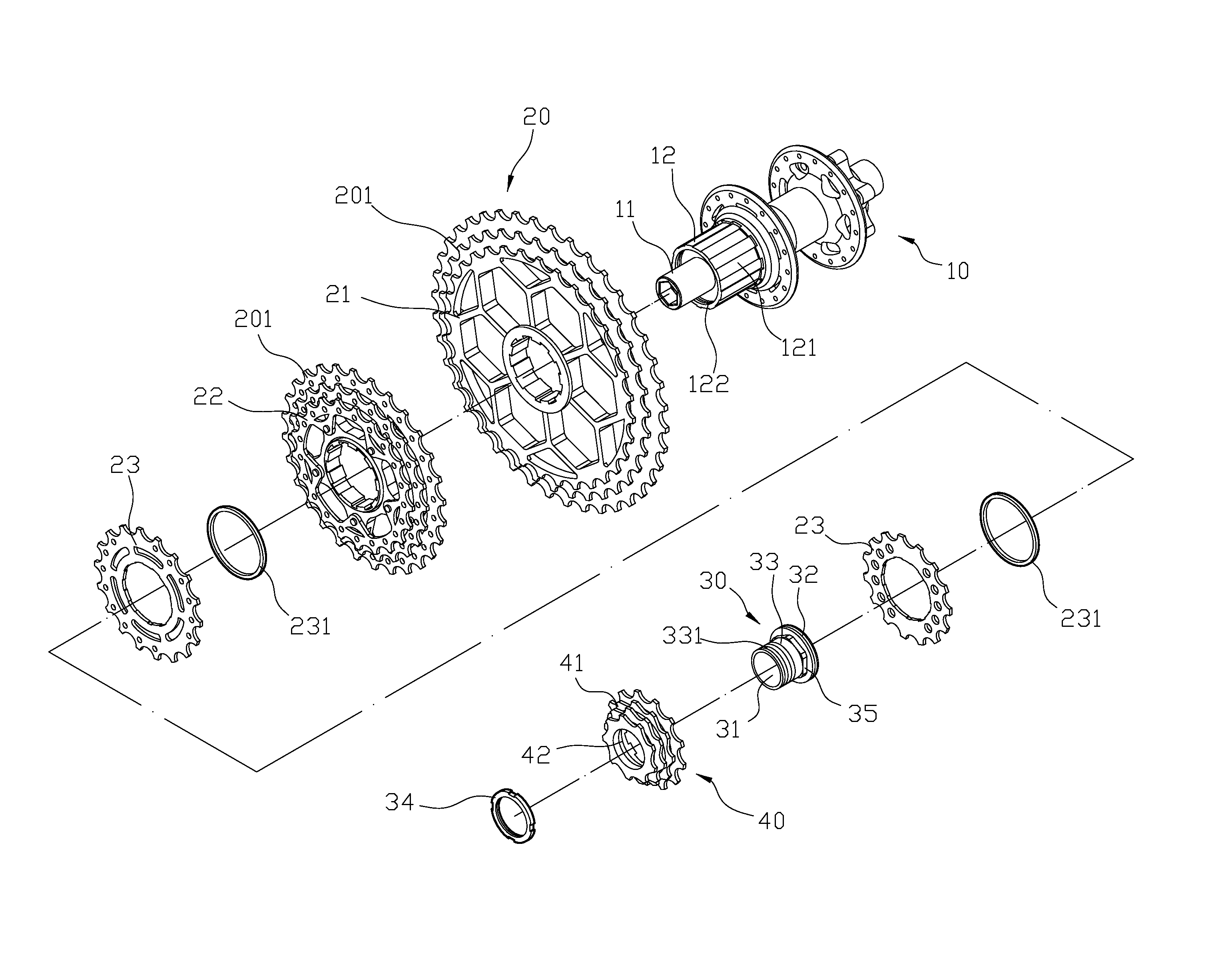
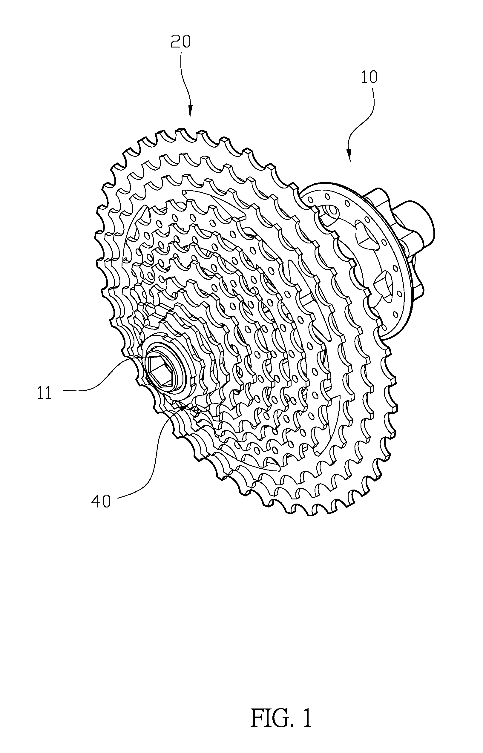
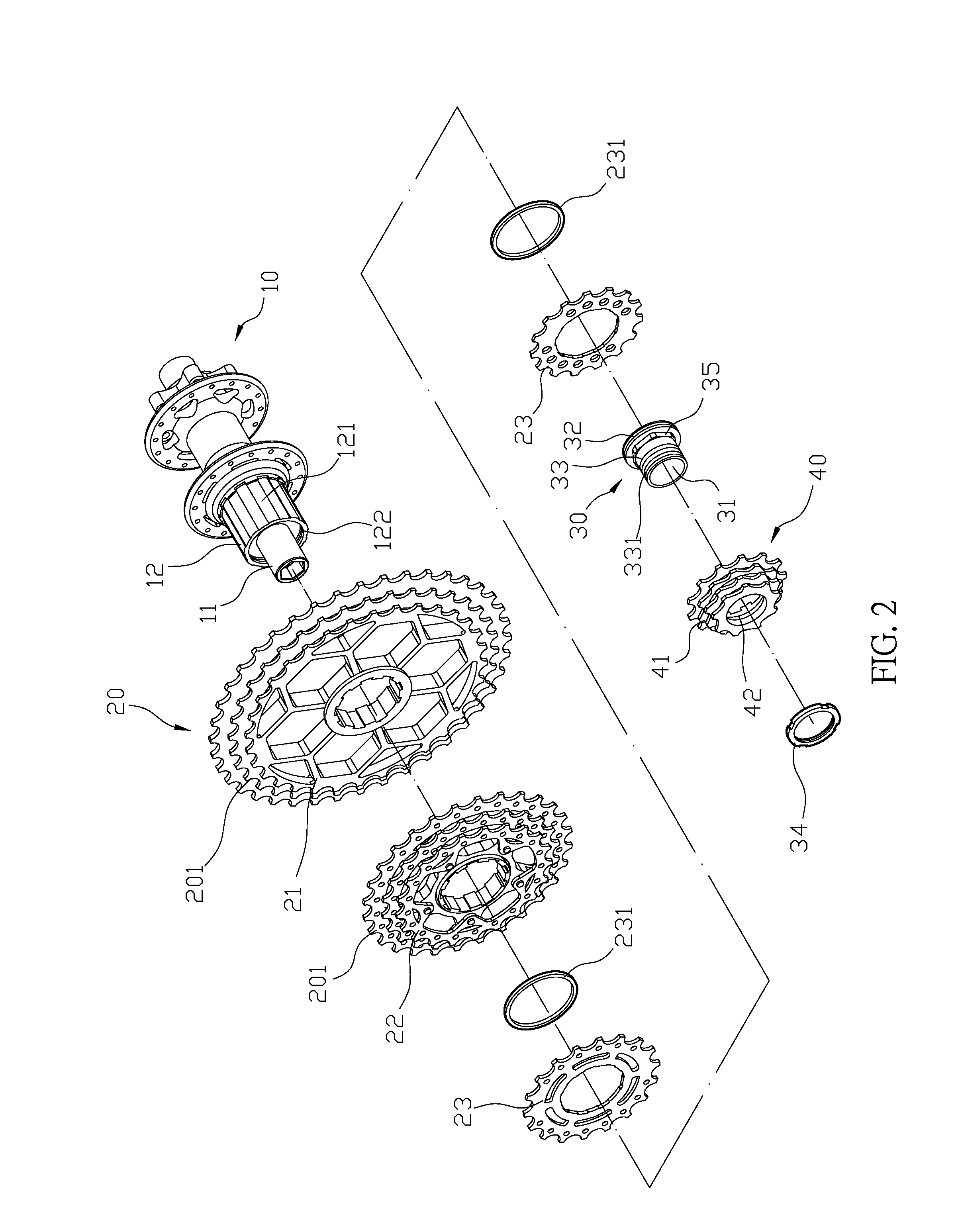
The present invention is an improvement on conventional bicycle hubs because it allows for a more efficient and easy-to-assemble freewheel unit. The connecting sleeve and external freewheel unit design also allows for faster pedaling speeds on downhill bicycles by increasing the number of smaller freewheels while reducing the number of teeth on the minimum sprocket. This design helps cyclists maintain an optimal pedaling speed and reduces the risk of chain falling off when riding in urban or narrow terrain.

Problems solved by technology

However, the conventional bicycle hub apparatus is disadvantageous because: (i) on the market, the number and the minimum size of sprockets on the freewheel (60) is limited by the size of the ratchet sleeve (52).
When cycling downhill, the conventional minimum sprocket can only provide the pedaling speed for a slightly slopy terrain, and the speed of the bicycle is difficult to control when the slope of the terrain increases, so the risk of bicycle chain falling off is increased; and (ii) the acceleration of the bicycle by rotating the pedals is limited while the size of minimum sprocket is restricted, and the problem can only be solved by developing a suitable ratchet sleeve (52) which can fit the smaller sprockets.
However, the solution mentioned above increases the costs of production and research and development.

Method used


Image

  • Bicycle hub and flywheel structure
  • Bicycle hub and flywheel structure
  • Bicycle hub and flywheel structure

Examples


Embodiment Construction

[0014]The detailed description set forth below is intended as a description of the presently exemplary device provided in accordance with aspects of the present invention and is not intended to represent the only forms in which the present invention may be prepared or utilized. It is to be understood, rather, that the same or equivalent functions and components may be accomplished by different embodiments that are also intended to be encompassed within the spirit and scope of the invention.

[0015]Unless defined otherwise, all technical and scientific terms used herein have the same meaning as commonly understood to one of ordinary skill in the art to which this invention belongs. Although any methods, devices and materials similar or equivalent to those described can be used in the practice or testing of the invention, the exemplary methods, devices and materials are now described.

[0016]All publications mentioned are incorporated by reference for the purpose of describing and disclos...


PUM


Abstract

An improved knife sharpener may include a hub body, a freewheel unit, a connecting sleeve and an external freewheel. The connecting sleeve connects to the ratchet sleeve of the hub body in order to provide more space for the external freewheel. With the design of the connecting sleeve and the external freewheel unit, the hub body loaded with more smaller freewheels provides more pedaling speeds for a bicycle travelling downhill. When cycling downhill by using the smaller diameters of the sprockets, the smaller sprockets of the external freewheel can help a cyclist to maintain an optimum pedaling speed in a slopy terrain, and the speed of the bicycle can be easily controlled.

Description

FIELD OF THE INVENTION[0001]The present invention relates to a bicycle hub and flywheel structure, and more particularly to a bicycle hub and flywheel structure that can be used for a bicycle travelling downhill.BACKGROUND OF THE INVENTION[0002]Generally, most bicycles have a derailleur system which can force the chain to shift between different sprockets in order to achieve a variable gear ratio, so a cyclist can maintain an optimum pedaling speed while covering varied terrain. A conventional bicycle hub apparatus includes a freewheel, a sprocket unit, a derailleur, a chain, a shift lever and a cable. The sprocket unit includes two to three pieces of sprockets formed on a crank portion of a bicycle, and the chain engaged on one of the sprocket of the sprocket unit is shifted between sprockets by operating the shift lever. The freewheel includes five to ten pieces of sprockets mounted on the hub of rear bicycle wheel, and the chain engaged on one of the sprockets of freewheel is shi...

Claims


Application Information

Patent Timeline
IPC IPC(8): B60B27/00B60B27/04B62M9/121B60B27/02
CPCB60B27/0026B62M9/121B60B27/047B60B27/023B60B2900/531B60B2900/541F16H55/12
Inventor CHEN, CHING-SHU
Owner CHOSEN
Learn More