Aluminum alloy oil pump shell trimming die

A technology of oil pump and aluminum alloy, which is applied in metal processing and other fields, can solve the problems of high risk, heavy workload, and low work efficiency, and achieve the effects of safe operation, high work efficiency, and easy cleaning

Pending Publication Date: 2019-12-03
LIANHE HOUPU TAICANG PRECISION MACHINERY CO LTD
0 Cites 0 Cited by

AI-Extracted Technical Summary

Problems solved by technology

[0003] The burr of the oil pump casing can be cut off with a grinding wheel and a chisel. Due to the complex structure of the oil pump casing, there are many burrs, the workload is large, and the work...

Method used

A kind of trimming die of aluminum alloy engine oil pump housing, comprising: movable mold base 6, fixed mold base 13, fixed plate 1, first floating plate 3, second floating plate 14, floating frame 9, punch are installed plate 7 and several trimming punches 17, the fixed plate 1 is arranged on the top of the movable mold base 6, and the bottom of the fixed mold base 13 is provided with a foot support block 19, which facilitates the fixing of the fixed mold base 13. A column is arranged between the fixed plate 1 and the movable mold base 6 for connection 18, and the structure is stable.
Described movable mold base 6 is provided with 4 guide sleeves 16 pointing downwards, described fixed mold base 13 is provided with guide rod 15 corresponding with guide sleeve 16, the cooperation of guide sleeve 16 and guide rod 15, The stability of mold clamping and mold opening has been improved. The floating frame 9 is provided with guide holes corresponding to the guide rods 15, which ensures the accuracy of the floating frame 9 moving up and down and avoids deflection.
Described trimming punch 17 is respectively fixed on the below of punch mounting plate 7, and described trim...

Abstract

The invention discloses an aluminum alloy oil pump shell trimming die. The trimming die comprises a movable die base, a fixed die base, a fixed plate, a first floating plate, a second floating plate,a floating frame, a punch mounting plate and a plurality of trimming punches, a first spring connected with the first floating plate is arranged at the bottom of the fixed plate; the trimming punchesare respectively fixed below the punch mounting plate; a waist-shaped hole is formed in the top of each trimming punch, a shell pressing block is arranged below the second floating plate, a shell supporting block is arranged on the fixed die base, through grooves corresponding to the bottoms of the trimming punches are formed in the shell supporting block, and floating block extending into the through grooves are arranged in the floating frame. By means of the mode, according to the invention, when the movable die base is pressed downwards, the shell pressing block makes contact with the upperportion of the aluminum alloy oil pump shell to be pressed and fixed, the trimming punches cooperate with the through grooves to cut off burrs, and the cut burrs fall into the through grooves.

Application Domain

Metal working apparatus

Technology Topic

EngineeringAluminium alloy

Image

  • Aluminum alloy oil pump shell trimming die

Examples

  • Experimental program(1)

Example Embodiment

[0015] The technical solutions in the embodiments of the present invention will be described clearly and completely below. Obviously, the described embodiments are only a part of the embodiments of the present invention, rather than all the embodiments. Based on the embodiments of the present invention, all other embodiments obtained by those of ordinary skill in the art without creative work shall fall within the protection scope of the present invention.
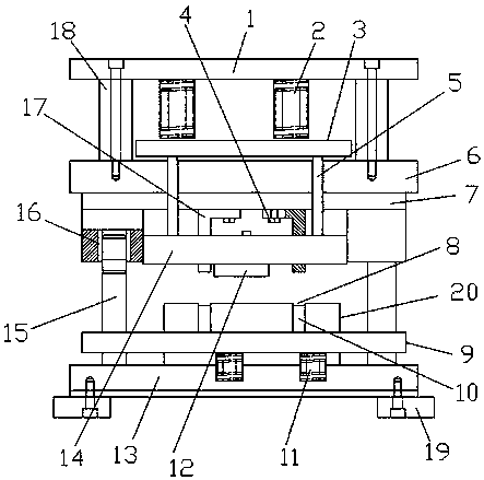
[0016] See figure 1 , The embodiment of the present invention includes:
[0017] An aluminum alloy oil pump shell trimming die, including: a movable die seat 6, a fixed die seat 13, a fixed plate 1, a first floating plate 3, a second floating plate 14, a floating frame 9, a punch mounting plate 7 and Several edge trimming punches 17, the fixed plate 1 is arranged above the movable mold base 6, and the bottom of the fixed mold base 13 is provided with a foot support block 19, which facilitates the fixing of the fixed mold base 13. A column 18 is arranged between the movable mold base 6 and the structure is stable.
[0018] The first floating plate 3 is located between the fixed plate 1 and the movable mold base 6, the bottom of the fixed plate 1 is provided with a first spring 2 connected to the first floating plate 3, and the punch mounting plate 7 is located on the movable mold base. At the bottom of the mold base 6, the second floating plate 14 is located below the punch mounting plate 7, and the second floating plate 14 is provided with a long rod bolt 5 connected to the first floating plate 3 to facilitate the first floating Floating and resetting of the plate 3 and the second floating plate 14.
[0019] The edge trimming punches 17 are respectively fixed below the punch mounting plate 7, the edge trimming punch 17 is an L-shaped bent plate, the top of the edge trimming punch 17 is provided with a waist hole, the edge trimming punch A fastening bolt 4 that passes through the waist hole and is connected to the punch mounting plate 7 is provided on the 17 to facilitate the position adjustment of the edge trimming punch 17.
[0020] A housing pressing block 12 is provided under the second floating plate 14, a housing support block 20 is provided on the fixed mold base 13, and the aluminum alloy oil pump housing is placed on the housing support block 20 and used after mold clamping. The shell pressing block 12 is pressed and fixed, with small impact, high stability and avoiding damage.
[0021] The housing support block 20 is provided with a through groove 8 corresponding to the bottom of the trimming punch 17, the floating frame 9 is located outside the housing support block 20, and the fixed mold base 13 is provided with a bottom of the floating frame 9 In the second spring 11 connected, the floating frame 9 is provided with a floating block 10 extending into the through slot 8. After the mold is opened, the floating block 10 rises to push out the burrs in the through slot 8.
[0022] The movable mold base 6 is provided with four guide sleeves 16 pointing downward, and the fixed mold base 13 is provided with a guide rod 15 corresponding to the guide sleeve 16. The cooperation of the guide sleeve 16 and the guide rod 15 improves the fit Stability of mold and mold opening. The floating frame 9 is provided with a guide hole corresponding to the guide rod 15 to ensure the accuracy of the up and down movement of the floating frame 9 and avoid deflection.
[0023] The bottom of the punch mounting plate 7 is arrayed with threaded holes corresponding to the fastening bolts 4 to facilitate the installation of the fastening bolts 4. The second floating plate 14 is provided with positioning bolts connected with the housing pressing block 12, and the installation and position adjustment of the housing pressing block 12 are relatively convenient.
[0024] In summary, the aluminum alloy oil pump shell trimming die pointed out in the present invention can cut the aluminum alloy oil pump shell burrs at one time, with high efficiency and good operational safety.
[0025] The above are only the embodiments of the present invention and do not therefore limit the scope of the present invention. Any equivalent structure or equivalent process transformation made by using the content of the present invention description, or directly or indirectly applied in other related technical fields, are all The same reason is included in the scope of patent protection of the present invention.

PUM

no PUM

Description & Claims & Application Information

We can also present the details of the Description, Claims and Application information to help users get a comprehensive understanding of the technical details of the patent, such as background art, summary of invention, brief description of drawings, description of embodiments, and other original content. On the other hand, users can also determine the specific scope of protection of the technology through the list of claims; as well as understand the changes in the life cycle of the technology with the presentation of the patent timeline. Login to view more.

Similar technology patents

LED wafer cleaning device

Owner:FOSHAN ZHENGLUE INFORMATION TECH CO LTD

Chopping board accessory with waste receptacle

ActiveUS9155427B1easy to cleaneasily store
Owner:KUMAR LAKSHMI

Classification and recommendation of technical efficacy words

  • Improve work efficiency
  • easy to clean

Cooperation service platform facing different source data

InactiveCN101174957AImprove management level and qualityImprove work efficiency
Owner:NANJING UNIV OF FINANCE & ECONOMICS

Screw drilling tool, vertical drilling tool testing method and well inclination simulation testing equipment

InactiveCN111594144AReduced height requirementsImprove work efficiency
Owner:DEZHOU UNITED GASOLINEEUM MACHINERY

Method for intelligent automatic identification of transmission circuit parts

Owner:INFORMATION COMM COMPANY STATE GRID SHANDONG ELECTRIC POWER +2

Keyboard spill-proofing mechanism

ActiveUS7030330B2minimize manufacturing costimprove work efficiency
Owner:LITE ON SINGAPORE PTE LTD

Collapsible pet housing

InactiveUS20050229866A1easily assembleeasy to clean
Owner:SIMPSON JEFFREY M

Steam floor mop

ActiveUS20070130719A1easy to cleanhigh temperature
Owner:SHARKNINJA OPERATING LLC

Convertible Clothing Article with Containment Pouch

ActiveUS20130042383A1easy to clean
Owner:PYFER CHRISTINE +1
Why Eureka
Try Eureka