
Clasp travel control device and control method of bra clasp machine

A technology of stroke control and buckle machine, which is applied in the direction of program-controlled sewing machines, cloth pressing mechanism, sewing machine components, etc. It can solve the problems of sewing asymmetry on the left and right sides of the suture, the decrease of suture quality, and affecting the appearance of the product, etc., to achieve Improving sewing quality, avoiding defective and waste products, feasible control effect

Pending Publication Date: 2019-12-03
NINGBO CHINKI SEWING MACHINE TECH CO LTD
View PDF0 Cites 0 Cited by
  • Summary
  • Abstract
  • Description
  • Claims
  • Application Information

AI Technical Summary

Problems solved by technology

However, since the actual width of all buckles cannot be guaranteed to be equal to the standard width preset by the machine, that is, there is often a certain deviation in the width of the buckles. Therefore, the center position of the actual feeding cannot coincide with the theoretical center position. During the sewing process, it is easy to appear that the sutures are sewn asymmetrically on the left and right sides of the buckle, resulting in a decrease in the quality of the sutures. The light ones affect the appearance of the product, and the severe ones produce waste products, resulting in waste of materials

Method used


Image

  • Clasp travel control device and control method of bra clasp machine
  • Clasp travel control device and control method of bra clasp machine
  • Clasp travel control device and control method of bra clasp machine

Examples


Embodiment Construction

[0022] The present invention will be further described in detail below in conjunction with the accompanying drawings and embodiments.

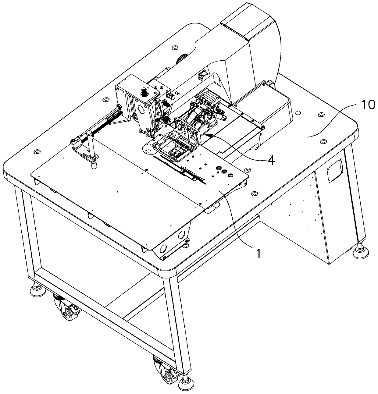
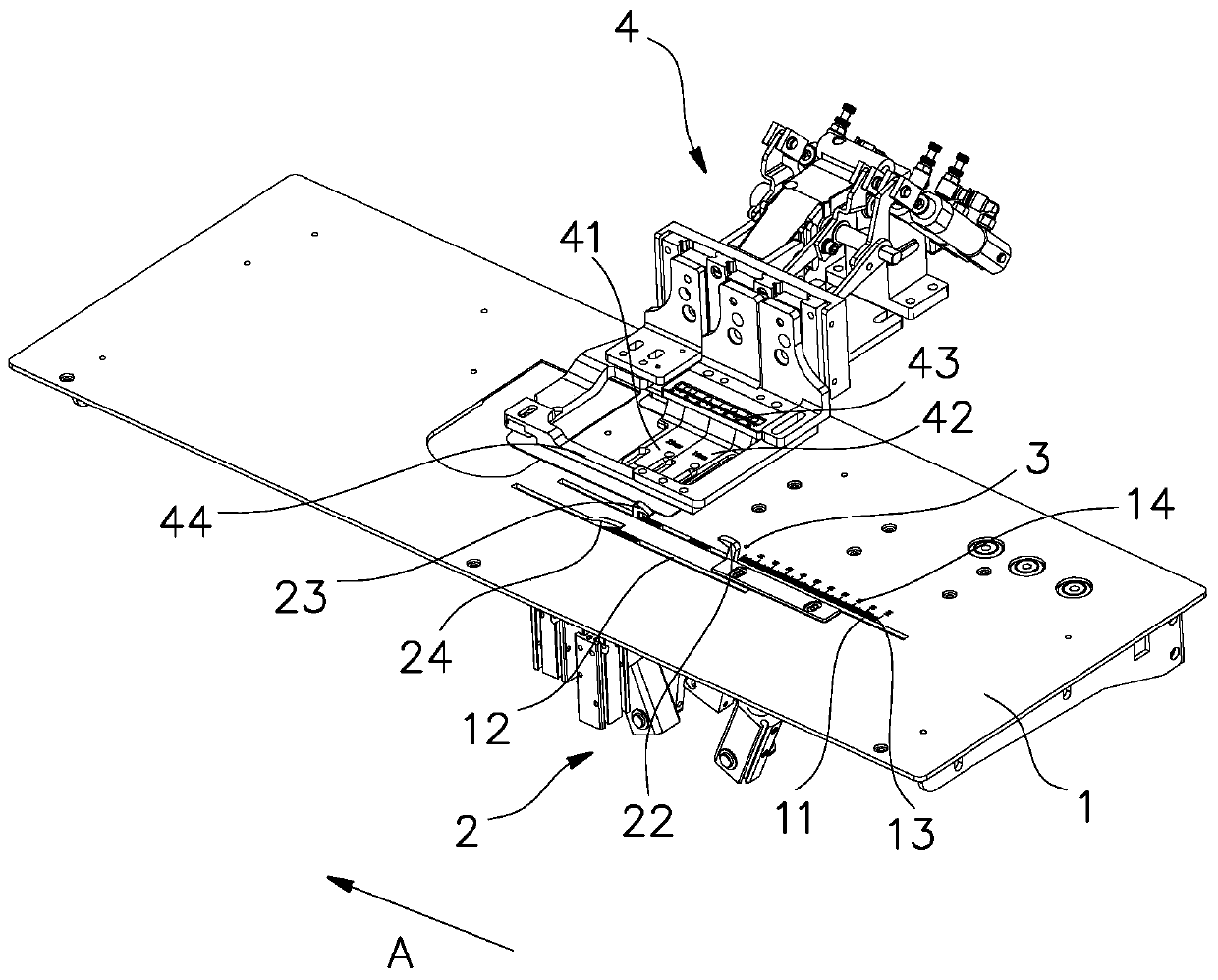
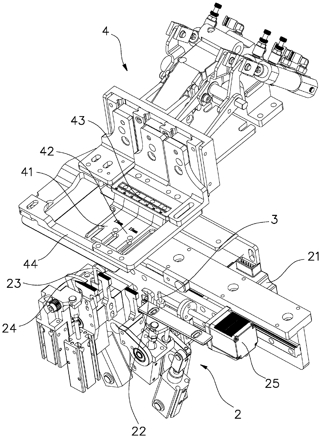
[0023] Such as Figure 1 to Figure 3 shown in figure 2 The direction shown by the middle arrow A is left, and the buckle travel control device of the bra buckle machine of the present embodiment includes an auxiliary plate 1 arranged on the frame 10, and a pressing mechanism 2 is installed below the auxiliary plate 1, and the pressing The mechanism 2 has a pressing block that can protrude upwards from the auxiliary board 1 and press the buckle on the table surface of the auxiliary board. The pressing mechanism 2 drives the buckle to move from the initial positioning position to the feeding position. The control device also includes a photoelectric detection device 3 and a controller (shown in the figure) electrically connected to the photoelectric detection device. The photoelectric detection device 3 is arranged between the initial position...


PUM


Abstract

The invention relates to a clasp travel control device of a bra clasp machine. A material pressing mechanism is arranged below an auxiliary plate, the material pressing mechanism is provided with a material pressing block capable of pressing clasps on an auxiliary plate table surface, and the material pressing mechanism drives the clasps to move from an initial positioning position to a feeding position. The device further comprises a photoelectric detection device and a controller. The photoelectric detection device can send corresponding electric signals to the controller in the process thatthe opposite side edges of the clasps in the width direction sequentially pass through the photoelectric detection device, and the controller can obtain the clasp width according to the received electric signals and correspondingly control the moving distance of the clasps from the initial positioning position to the feeding position. The controller of the clasp travel control device of the bra clasp machine can obtain the actual width of the clasps according to the received electric signals and determine the actual moving distance of the clasps, so that the center position of the actual feeding position coincides with a theoretical center position; a control method is simple, feasible and accurate in control, and sewing in the subsequent sewing procedure is more accurate, so that the sewing quality is improved.

Description

technical field [0001] The invention relates to a bra buckle machine, in particular to a buckle stroke control device and a control method of the bra buckle machine. Background technique [0002] During the bra manufacturing process, it is necessary to sew the straps with the buckle and the back straps of the bra together. At present, the straps are usually connected to the straps manually, and then placed on the sewing machine for manual sewing. This processing method is not only inefficient, but also has high labor costs, and the quality of the processed bra straps is not uniform enough, and it is easy to form defective products. . In order to improve work efficiency and product quality, people invented bra buckle sewing machines. Bra buckle sewing machines usually include a pressing mechanism, a buckle positioning mechanism, a feeding mechanism and a sewing machine head, wherein the pressing mechanism is used to press the strap and strap to be sewn, so that the feeding ...

Claims


Application Information

Patent Timeline
IPC IPC(8): D05B19/16D05B19/08D05B29/00D05B39/00
CPCD05B19/16D05B19/08D05B29/00D05B39/00D05D2305/36
Inventor 张标
Owner NINGBO CHINKI SEWING MACHINE TECH CO LTD
Features
  • Generate Ideas
  • Intellectual Property
  • Life Sciences
  • Materials
  • Tech Scout
  • Unparalleled Data Quality
  • Higher Quality Content
  • 60% Fewer Hallucinations
Learn More