A reservoir water level monitoring device

A monitoring device and a technology for reservoir water level, which are applied to measurement devices, sampling devices, lubrication indicating devices, etc., can solve the problems of inconvenient monitoring of reservoir water level depth, inconvenient to monitor reservoir silt depth, inconvenient to collect silt samples, etc. The detection is convenient and quick, the safety performance is improved, and the contact area is increased.

Active Publication Date: 2021-01-01
四川蜀江建设工程项目管理有限公司
View PDF9 Cites 1 Cited by
  • Summary
  • Abstract
  • Description
  • Claims
  • Application Information

AI Technical Summary

Problems solved by technology

[0003] However, the water level signs of the traditional reservoir are fixed at a fixed position, which is not convenient for monitoring the water level depth in different positions in the reservoir, and does not have the function of monitoring the silt depth in the reservoir, and the net water level depth of the reservoir cannot be predicted. When the inside of the reservoir When there is too much silt, if the silt is not cleaned up in time, it will easily affect the flood storage capacity of the reservoir. At the same time, it is not convenient to collect silt samples deep in the reservoir, and it is not convenient to monitor the environmental quality of the reservoir.

Method used


Image

  • A reservoir water level monitoring device
  • A reservoir water level monitoring device
  • A reservoir water level monitoring device

Examples


Embodiment Construction

[0026] In order to make the technical means, creative features, goals and effects achieved by the present invention easy to understand, the present invention will be further described below in conjunction with specific embodiments.

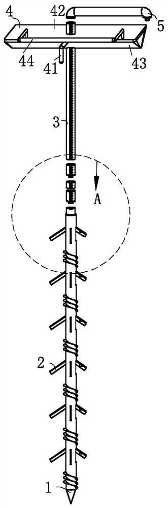
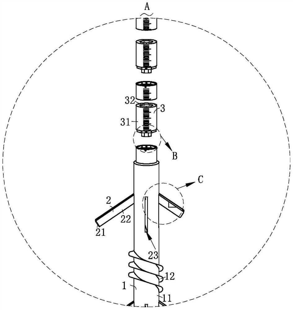
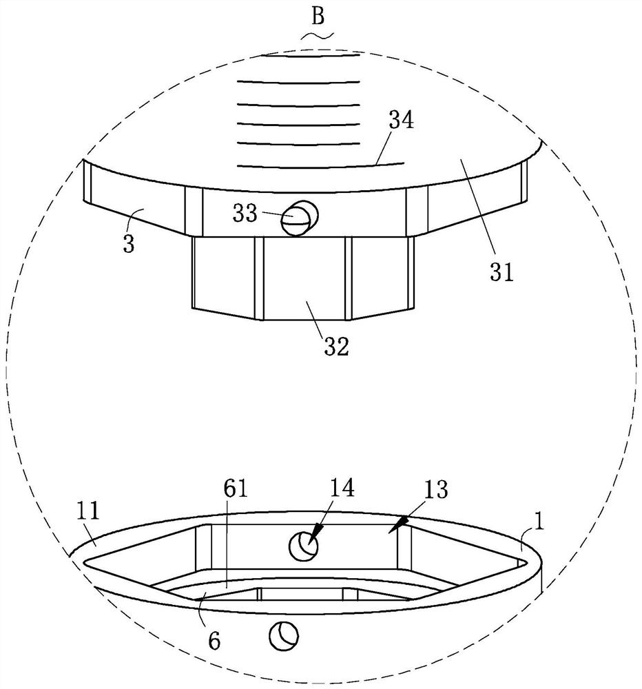
[0027] Such as Figure 1-Figure 8As shown, a reservoir water level monitoring device according to the present invention includes a driving structure 1, a sampling structure 2, a measuring structure 3, a supporting structure 4, a driving handle 5 and a driving structure 6; The top of the excavation structure 1 is provided with a plurality of said measuring structures 3, and the adjacent two said measuring structures 3 are detachably connected, and said measuring structures 3 used for measuring the water level depth in different positions of the reservoir are connected with said measuring structures 3. The driving structures 1 are detachably connected; the supporting structure 4 is fixed on one of the measuring structures 3 away from the end of the ...


PUM


Abstract

The invention relates to the field of water level monitoring devices, in particular to a reservoir water level monitoring device which comprises a tunneling structure, a sampling structure, a measuring structure, a supporting structure, a driving handle and a driving structure. The tunneling structure is arranged at the end portion of a measuring structure deviating from the most end portion of the supporting structure; and thus the measuring structure rotated helically conveniently to drive the tunneling structure to be inserted into reservoir sludge. A distance between the position, bonded to the tunneling structure, of the sludge and the position, making contact with the liquid level, of the measuring structure is equal to the water level depth of the reservoir; and the length of the position of the sludge bonded to the tunneling structure is equal to the depth of the sludge. The sampling structure is arranged in the tunneling structure and is connected to the driving structure andthus the driving structure is conveniently driven by the measuring structure to drive the sampling structure to sample the sludge in the reservoir, so that the sludge at different depths is conveniently collected. Whether heavy metal in the sludge in the reservoir exceeds the standard or not is conveniently observed, so that the reservoir is conveniently treated in time according to sludge detection data of the reservoir.

Description

technical field [0001] The invention relates to the field of water level monitoring devices, in particular to a reservoir water level monitoring device. Background technique [0002] Reservoirs are generally interpreted as "hydraulic engineering structures that hold back flood water and regulate water flow, and can be used for irrigation, power generation, flood control and fish farming." It refers to artificial lakes formed by building dams at the narrow mouths of ravines or rivers . After the reservoir is completed, it can play the roles of flood control, water storage for irrigation, water supply, power generation, fish farming, etc. There are water level signs installed in the reservoir, and the water level of the reservoir can be predicted through the scale of the sign on the reservoir. [0003] However, the water level signs of the traditional reservoir are fixed at a fixed position, which is not convenient for monitoring the water level depth in different positions i...

Claims


Application Information

Patent Timeline
Patent Type & Authority Patents(China)
IPC IPC(8): G01F23/00G01N1/10
CPCG01F23/00G01N1/10G01N2001/1025
Inventor 不公告发明人
Owner 四川蜀江建设工程项目管理有限公司
Why Eureka
Try Eureka