Lighting Module and Display Module

A light-emitting module and display module technology, which is applied in the direction of identification devices, instruments, semiconductor devices, etc., can solve the problems of affecting viewing quality, inconsistency in color light output, and failure to display pictures, etc., to achieve good display quality, reduce area, and avoid invalid display areas Effect

Active Publication Date: 2021-05-28
AU OPTRONICS CORP
View PDF6 Cites 0 Cited by
  • Summary
  • Abstract
  • Description
  • Claims
  • Application Information

AI Technical Summary

Problems solved by technology

Therefore, when a user uses the above-mentioned large-size display panel, it will cause inconsistencies in the output of colored light, thereby affecting the display quality.
[0003] On the other hand, in each smaller display panel, there are usually a display area and a frame area, and the display area is provided with display pixels and some wires, and the frame area is used to set the driving circuit, Part of the wiring or the area of ​​other electronic components, so the frame area (or invalid display area / non-display area) usually cannot display the picture
After the splicing is completed, there will be invalid display areas between these smaller display panels, resulting in the discontinuity of the overall display screen, which will affect the viewing quality

Method used


Image

  • Lighting Module and Display Module
  • Lighting Module and Display Module
  • Lighting Module and Display Module

Examples


Embodiment Construction

[0086] Below in conjunction with accompanying drawing, structural principle and working principle of the present invention are specifically described:

[0087] In order to facilitate the description of the configuration relationship between the display module and the light-emitting module in the embodiment of the present invention, the display module and the light-emitting module in the embodiment of the present invention can be regarded as being in a three-dimensional space composed of directions D1, D2, and D3, wherein the direction D1 , D2 and D3 are perpendicular to each other.

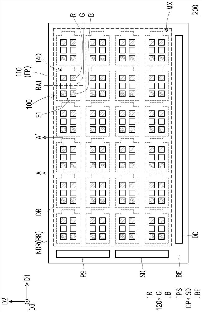
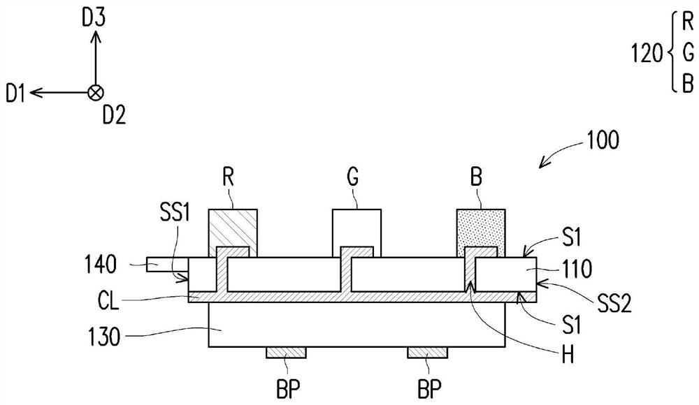
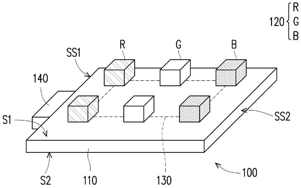
[0088] figure 1 It is a schematic top view of a display module according to an embodiment of the present invention. figure 2 yes figure 1 Schematic diagram of the cross-section of the light-emitting module. image 3 yes figure 1 Schematic diagram of the front of the light-emitting module. Figure 4 yes figure 1 Schematic diagram of the back of the light-emitting module. Figure 5 yes figu...


PUM

PropertyMeasurementUnit
sizeaaaaaaaaaa

Abstract

A light-emitting module includes a carrier substrate, a plurality of light-emitting elements, a module controller and an alignment part. The carrier substrate has a first surface, a second surface and a side surface. These light emitting elements are arranged on the first surface. The module controller is disposed on the second surface. The module controller is electrically connected with the light emitting elements. The alignment part is located on the side of the carrier substrate. The outer contour formed by the alignment part and the carrier substrate is asymmetrical. Another light emitting module and a display module are also proposed.

Description

technical field [0001] The invention relates to a light emitting module and a display module. Background technique [0002] The large-screen display system can centrally display signals from a variety of different signal sources to meet the needs of users to display various shared and comprehensive information in a large area. In a common practice, a plurality of smaller display panels are usually spliced ​​to form a large-sized display panel. In the display area of ​​each smaller display panel, usually the red light, blue light and green light emitting elements in the display area are arranged in a sequence and along a direction. Ideally, these light-emitting elements should be arranged in a specific sequence. However, since there is no obvious mark on the general light-emitting element to indicate its light-emitting color, it is possible to arrange the light-emitting elements of the same light-emitting color together during the splicing process, which will cause the same...

Claims


Application Information

Patent Timeline
Patent Type & Authority Patents(China)
IPC IPC(8): H01L25/075G09F9/33
CPCG09F9/33H01L25/0753
Inventor 戴君涵卢敏曜谢祥圆庄锦棠
Owner AU OPTRONICS CORP
Why Eureka
Try Eureka