
Electrician high-voltage line walking device

A technology for traveling devices and high-voltage lines, which is applied in the direction of overhead lines/cable equipment, etc., and can solve problems such as difficult line maintenance, poor personal safety protection for professionals, and ice disasters on long-distance transmission lines

Inactive Publication Date: 2019-12-03
NANJING YUQUN COMM TECH CO LTD
View PDF8 Cites 1 Cited by
  • Summary
  • Abstract
  • Description
  • Claims
  • Application Information

AI Technical Summary

Problems solved by technology

[0002] With the rapid development of my country's economy, more and more ultra-high-voltage large-capacity transmission lines are built, and the geographical environment that the lines cross during long-distance high-voltage line transmission is more complicated, such as passing through large-scale reservoirs, lakes and mountains, which brings many difficulties to line maintenance. , as the frequency and intensity of extreme weather and climate events caused by global warming increase significantly, and the geological conditions of transmission lines are complex, it is easier for long-distance transmission lines to be affected by extreme weather such as ice disasters, especially in southern my country Some provinces and cities often suffer from low temperature, rain and snow, and freezing disasters at the end of winter and early spring. The icicles became stronger, causing major damage to transmission lines and causing large-scale economic losses
[0003] When the existing high-voltage lines are in use, professionals usually need to regularly check whether there are some safety hazards in the high-voltage lines. The walking device not only has a simple structure and a single function, but also has poor protection for the personal safety of professionals during the inspection process

Method used


Image

  • Electrician high-voltage line walking device
  • Electrician high-voltage line walking device
  • Electrician high-voltage line walking device

Examples


Embodiment Construction

[0028] The following will clearly and completely describe the technical solutions in the embodiments of the present invention with reference to the accompanying drawings in the embodiments of the present invention. Obviously, the described embodiments are only some, not all, embodiments of the present invention.

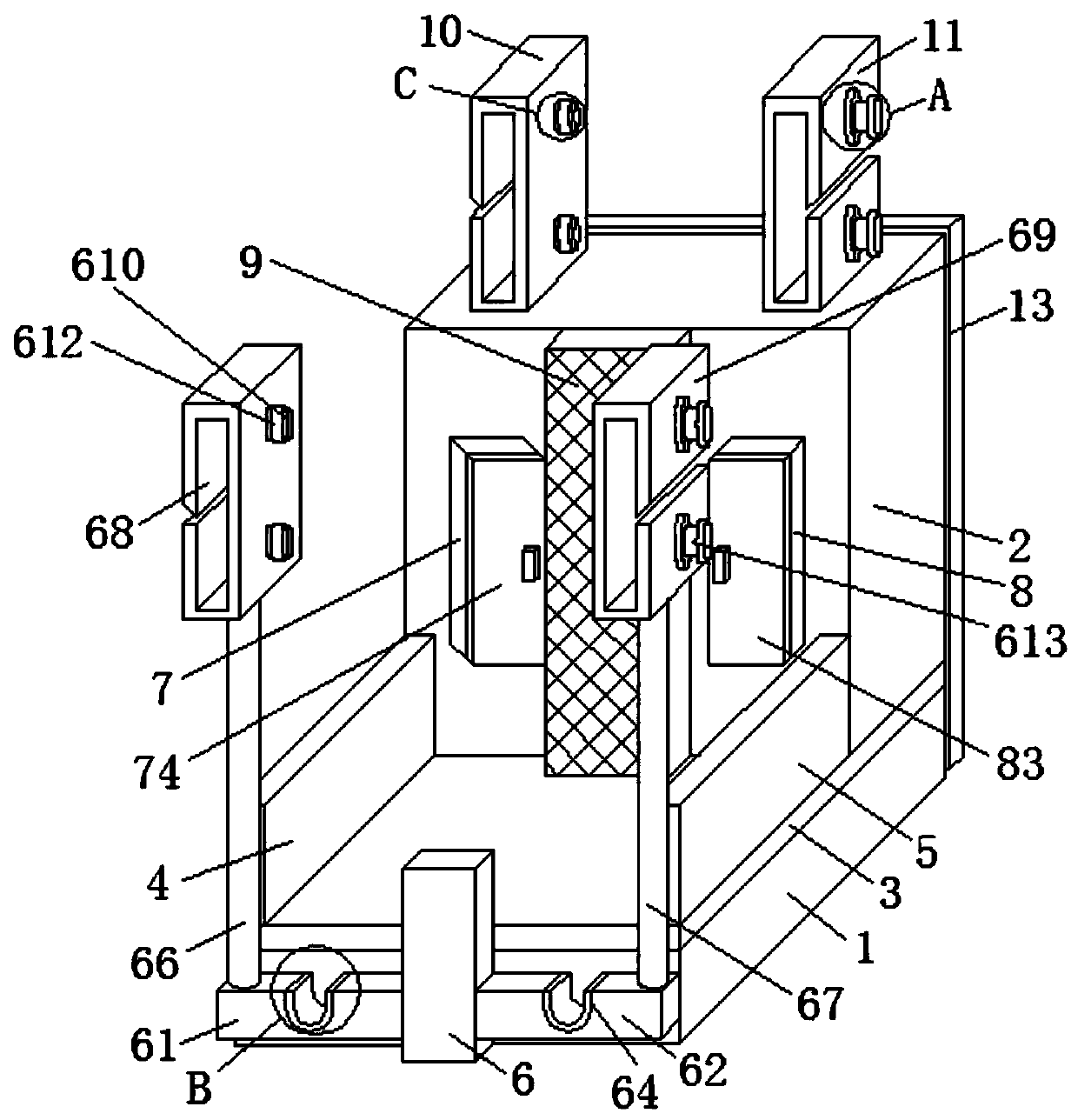
[0029] refer to Figure 1-8 , an electrical high-voltage line running device, comprising a first support plate 1 and a second support plate 2, a mica layer 3 is fixedly installed on the top of the first support plate 1;

[0030] Further, mica is provided inside the mica layer 3 , and the bottom of the mica layer 3 is adapted to the top of the first support plate 1 .

[0031] Further, the purpose of setting the mica layer 3 is to insulate the professional's legs.

[0032] Further, the method for making the mica layer 3 includes raw material preparation; Step 1, raw material preparation, the raw materials include quartz sand, alumina, fused magnesia, potassium fluoros...


PUM


Abstract

The invention belongs to the high voltage line field technology field and especially relates to an electrician high-voltage line walking device. The device comprises a first supporting plate and a second supporting plate. A mica layer is fixedly installed at a top of the first supporting plate. By using the electrician high-voltage line walking device, a second walking device is arranged on an upper surface of the second supporting plate, and the second walking device includes a third function cabinet and a fourth function cabinet. A bottom of the third function cabinet is fixedly connected with the upper surface of the second supporting plate, and the bottom of the fourth function cabinet is fixedly connected with the upper surface of the second supporting plate so that an effect that thesecond walking device divides pressure for a first walking device when a professional is overweight in a using process of the device is achieved. A problem that when the professional uses the deviceto inspect a high-voltage line, the first walking device is only arranged so that if the first walking device is damaged, personal safety of the professional cannot be effectively protected is solved.

Description

technical field [0001] The invention relates to the technical field of high-voltage wires, in particular to an electrical high-voltage wire traveling device. Background technique [0002] With the rapid development of my country's economy, more and more ultra-high-voltage large-capacity transmission lines are built, and the geographical environment that the lines cross during long-distance high-voltage line transmission is more complicated, such as passing through large-scale reservoirs, lakes and mountains, which brings many difficulties to line maintenance. , as the frequency and intensity of extreme weather and climate events caused by global warming increase significantly, and the geological conditions of transmission lines are complex, it is easier for long-distance transmission lines to be affected by extreme weather such as ice disasters, especially in southern my country Some provinces and cities often suffer from low temperature, rain and snow, and freezing disasters ...

Claims


Application Information

Patent Timeline
Patent Type & Authority Applications(China)
IPC IPC(8): H02G1/02
CPCH02G1/02
Inventor 苏春柏潘香怡
Owner NANJING YUQUN COMM TECH CO LTD
Learn More