Image sensor and image acquisition system

An image sensor and acquisition circuit technology, applied in image communication, TV system components, TV and other directions, can solve problems such as application adverse effects, large readout delay, readout channel blocking, etc., to speed up data readout , reduce the readout delay, reduce the effect of blocking

Active Publication Date: 2019-12-03
OMNIVISION SENSOR SOLUTION (SHANGHAI) CO LTD
View PDF12 Cites 7 Cited by
  • Summary
  • Abstract
  • Description
  • Claims
  • Application Information

AI Technical Summary

Problems solved by technology

However, when there is a large amount of dynamic information in the field of view, such as detecting a fast moving object in the field of view, the pixel acquisition circuit array will generate a large number of events in a short period of time
Since the readout circuit has to scan and read each event one by one, the advantage of the low bandwidth of the dynamic vision sensor will not be obvious
In addition, the readout of each event takes a certain amount of time, which will cause the blockage of the readout channel, and a large number of events generated by the pixel acquisition circuit array need to be queued for readout, resulting in a large readout delay. The output delay causes the deviation of event time information, which will also adversely affect the back-end application

Method used


Image

  • Image sensor and image acquisition system
  • Image sensor and image acquisition system
  • Image sensor and image acquisition system

Examples


Embodiment 1

[0053] Embodiment 1-head flag bit

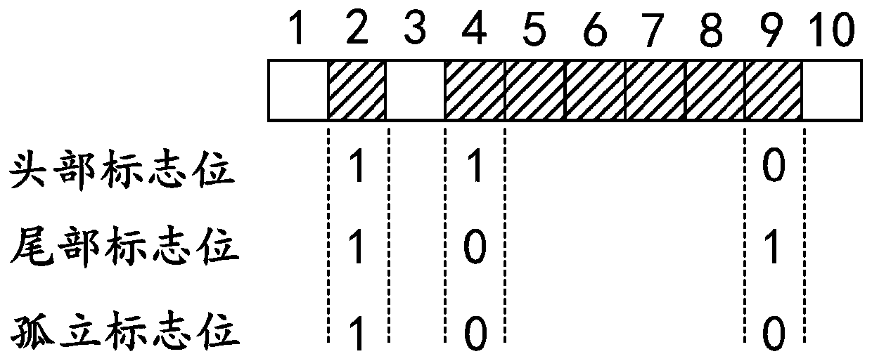
[0054] The head flag bit indicates that the trigger pixel acquisition circuit at the boundary is the beginning of some continuous trigger pixel acquisition circuits. The basis for judging is whether the left side adjacent to the boundary trigger pixel acquisition circuit is a pixel acquisition circuit in a trigger state, if it is not a pixel acquisition circuit in a trigger state, then the position of the head mark of the trigger pixel acquisition circuit at the boundary is 1; otherwise, set it to 0. Such as figure 2 , the head flag bits of the 2nd, 4th, and 9th border trigger pixel acquisition circuits are 1, 1, and 0, respectively.

Embodiment 2

[0055] Embodiment 2-Tail flag bit

[0056] The tail flag bit indicates that the trigger pixel acquisition circuit at the boundary is the end of some continuous trigger pixel acquisition circuits. The basis for judging is whether the right side adjacent to the trigger pixel acquisition circuit at the boundary is a pixel acquisition circuit in a triggered state. If the pixel acquisition circuit is not in the trigger state, the tail flag position of the trigger pixel acquisition circuit at the boundary is set to 1; otherwise, it is set to 0. Such as figure 2 , the tail flag bits of the 2nd, 4th, and 9th border trigger pixel acquisition circuits are 1, 0, and 1, respectively.

Embodiment 3

[0057] Embodiment 3-isolated flag bit

[0058] The isolated flag bit indicates that the trigger pixel acquisition circuit at the boundary is an isolated trigger pixel acquisition circuit. The basis for judging is whether the left side and the right side adjacent to the trigger pixel acquisition circuit at the border are pixel acquisition circuits in a triggered state. If none of them is a pixel acquisition circuit in a trigger state, the isolated flag position of the trigger pixel acquisition circuit at the boundary is set to 1; otherwise, it is set to 0. Such as figure 2 , the isolated flag bits of the 2nd, 4th, and 9th border trigger pixel acquisition circuits are 1, 0, 0 respectively.

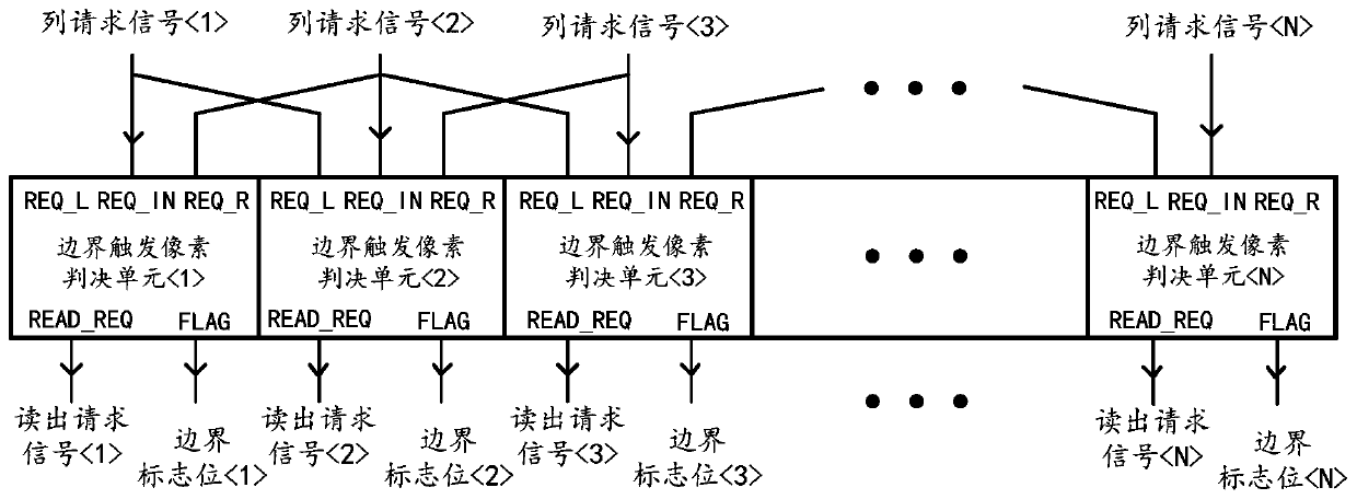
[0059] In order to further illustrate the working principle of the boundary trigger pixel decision array 120, image 3A schematic structural diagram of the boundary-triggered pixel decision array 120 according to an embodiment of the present invention is shown.

[0060] Such as image ...


PUM


Abstract

The invention discloses an image sensor and an image acquisition system. The image sensor comprises a pixel acquisition circuit array composed of a plurality of pixel acquisition circuits, and the pixel acquisition circuits are suitable for monitoring light intensity changes in a view field and entering a trigger state when the light intensity changes meet a certain condition; the boundary triggerpixel decision array is suitable for determining a trigger pixel acquisition circuit at the boundary from the pixel acquisition circuits at the trigger state; and the reading unit is suitable for responding to the trigger pixel acquisition circuit located at the boundary and outputting corresponding address information of the trigger pixel acquisition circuit.

Description

technical field [0001] The invention relates to the technical field of image acquisition, in particular to an image sensor and an image acquisition system. Background technique [0002] Among the many application fields of image sensors, the detection of moving objects is one of the important aspects. In this application field, compared with traditional image sensors (such as active pixel sensors), dynamic vision image sensors have gradually attracted people's attention because of their unique advantages. [0003] Dynamic vision image sensors (hereinafter referred to as dynamic vision sensors) only respond to dynamic information in the field of view and directly capture changes in light intensity in the field of view, so they are particularly suitable for applications in fields such as machine vision. In the dynamic vision sensor, each pixel acquisition circuit works independently and asynchronously, and is responsible for sensing the light intensity change in the field of ...

Claims


Application Information

Patent Timeline
Patent Type & Authority Applications(China)
IPC IPC(8): H04N5/369H04N5/378H04N5/345
CPCH04N25/44H04N25/70H04N25/75H04N25/40H04N25/50H04N25/74H04N25/767H04N25/778
Inventor 陈守顺郭梦晗
Owner OMNIVISION SENSOR SOLUTION (SHANGHAI) CO LTD
Why Eureka
Try Eureka