Siphon-type irrigation and drainage integrated cultivation device
A technology for irrigation and drainage, cultivation device, applied in the field of plant cultivation, can solve the problems of long-term submersion of root and seedling, drowning of plants, unfavorable cultivation cost and the like
- Summary
- Abstract
- Description
- Claims
- Application Information
AI Technical Summary
Problems solved by technology
Method used
Image
Examples
Embodiment 1
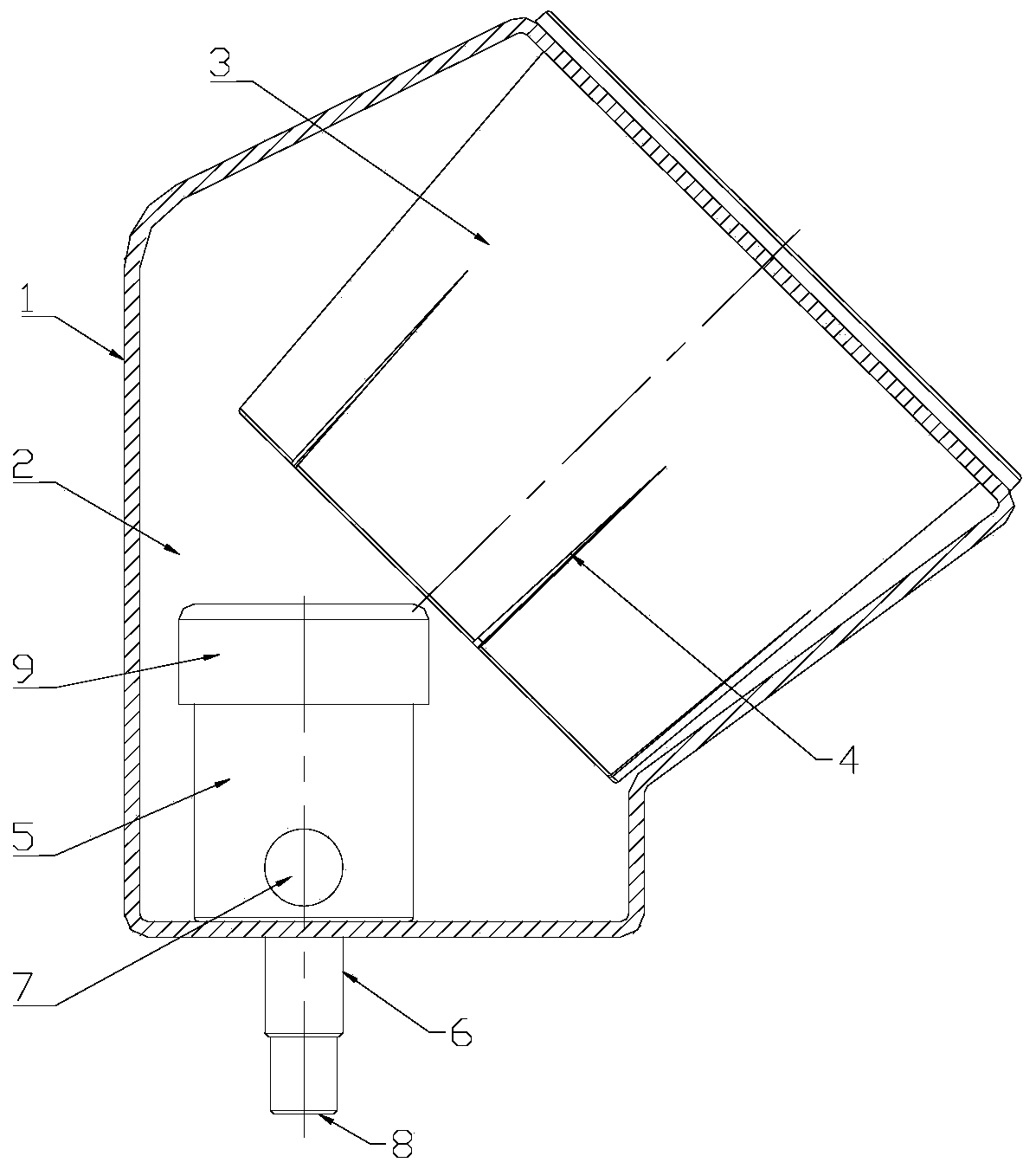
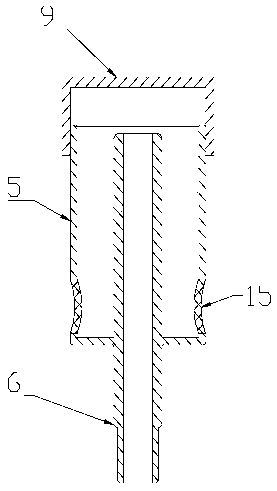
[0021] Such as Figure 1-2 As shown, a siphon irrigation and drainage integrated cultivation device includes a cultivation pipe 1 and a siphon irrigation and drainage integrated structure.
[0022] The cultivation pipe is supported by a vertical frame, the two ends of the cultivation pipe are closed, and the inner space of the cultivation pipe forms a water storage chamber 2, which is supplied with water by an external water supply device or manually added water, and the side walls of the cultivation pipe are spaced apart along the length direction. A plurality of planting cup placement holes communicated with the water storage chamber, each planting cup placement hole is clamped and installed with a planting cup 3, seedlings are planted in the planting cup, the lower section of the planting cup is immersed in the water storage chamber, and the lower section of the planting cup is opened. There are seepage holes or seepage grooves 4.
[0023] The integrated siphonic irrigatio...
Embodiment 2
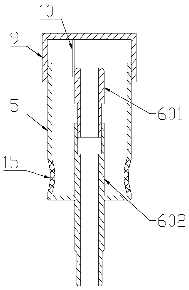
[0027] Compared with embodiment 1, the difference of this embodiment is: as image 3 As shown, the upper section of the inner tube body 6 seals through the center of the bottom of the outer cylinder body 5 and is socketed with the outer cylinder body. Body 601 and lower tube body 602, specifically, the lower section of upper tube body 601 is inserted into lower tube body 602 and threaded with the lower tube body. Connecting rod 10. During actual use, rotate the cover body 9 to adjust the overlapping size of the external thread section of the cover body 9 and the outer cylinder body 5, so that the cover body 9 lifts up and down without detaching from the outer cylinder body 5. At this time, driven by the connecting rod 10, The upper pipe body 601 will also rotate relative to the lower pipe body 602 synchronously, so that the upper pipe body 601 can be raised and lowered relative to the lower pipe body 602, thereby adjusting the height of the top of the upper pipe body, that is...
Embodiment 3
[0029] Compared with the above-mentioned embodiment, the difference of this embodiment is: as Figure 4 As shown, the inner wall of the lower tube body 602 is pasted with a ring-shaped airbag layer 11, and the airbag layer 11 is connected with an inflatable nozzle 12 through an inflatable tube. The inflatable nozzle 12 is detachably provided with an inflatable bag 13. The air bag is an automatically inflated rubber air bag, and an inflation valve 14 is also arranged at the inflation mouth place. In the specific use process, open the inflation valve 14, squeeze the air bag 13 periodically, and inflate the air bag layer, adjust the inflation amount in the air bag layer 11, and change the expansion degree of the air bag layer 11, thereby adjusting the lower tube The inner diameter of the body can be adjusted to adjust the drainage rate, and the overall internal space of the inner pipe body 6 can also be changed, so as to adapt to irrigation needs more flexibly. Large, so that th...
PUM
 Abstract
Description
Claims
Application Information
 - R&D Engineer
- R&D Manager
- IP Professional
- Industry Leading Data Capabilities
- Powerful AI technology
- Patent DNA Extraction
Browse by: Latest US Patents, China's latest patents, Technical Efficacy Thesaurus, Application Domain, Technology Topic, Popular Technical Reports.
© 2024 PatSnap. All rights reserved.Legal|Privacy policy|Modern Slavery Act Transparency Statement|Sitemap|About US| Contact US: help@patsnap.com


