Intelligent wind-resistant bouncy castle
A castle and intelligent technology, applied in the field of intelligent wind-resistant inflatable castles, can solve the problems of large inflatable castles, blown up inflatable castles, and not very large, so as to increase wind resistance, reduce wind-affected area, and reduce quality Effect
- Summary
- Abstract
- Description
- Claims
- Application Information
AI Technical Summary
Problems solved by technology
Method used
Image
Examples
specific Embodiment approach
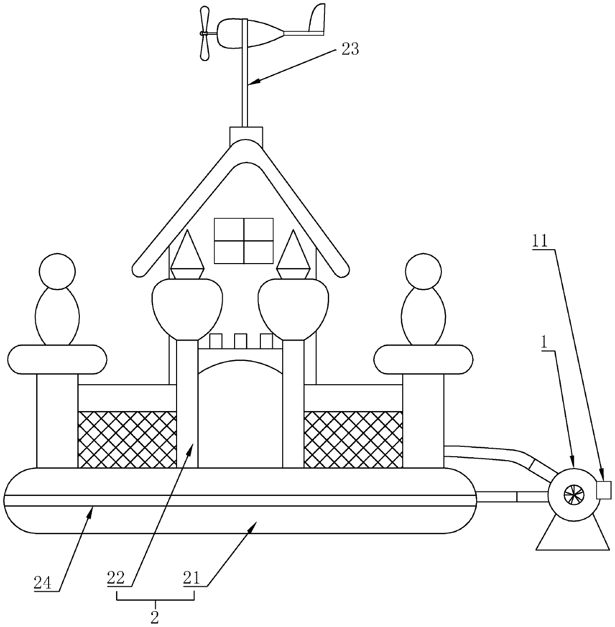
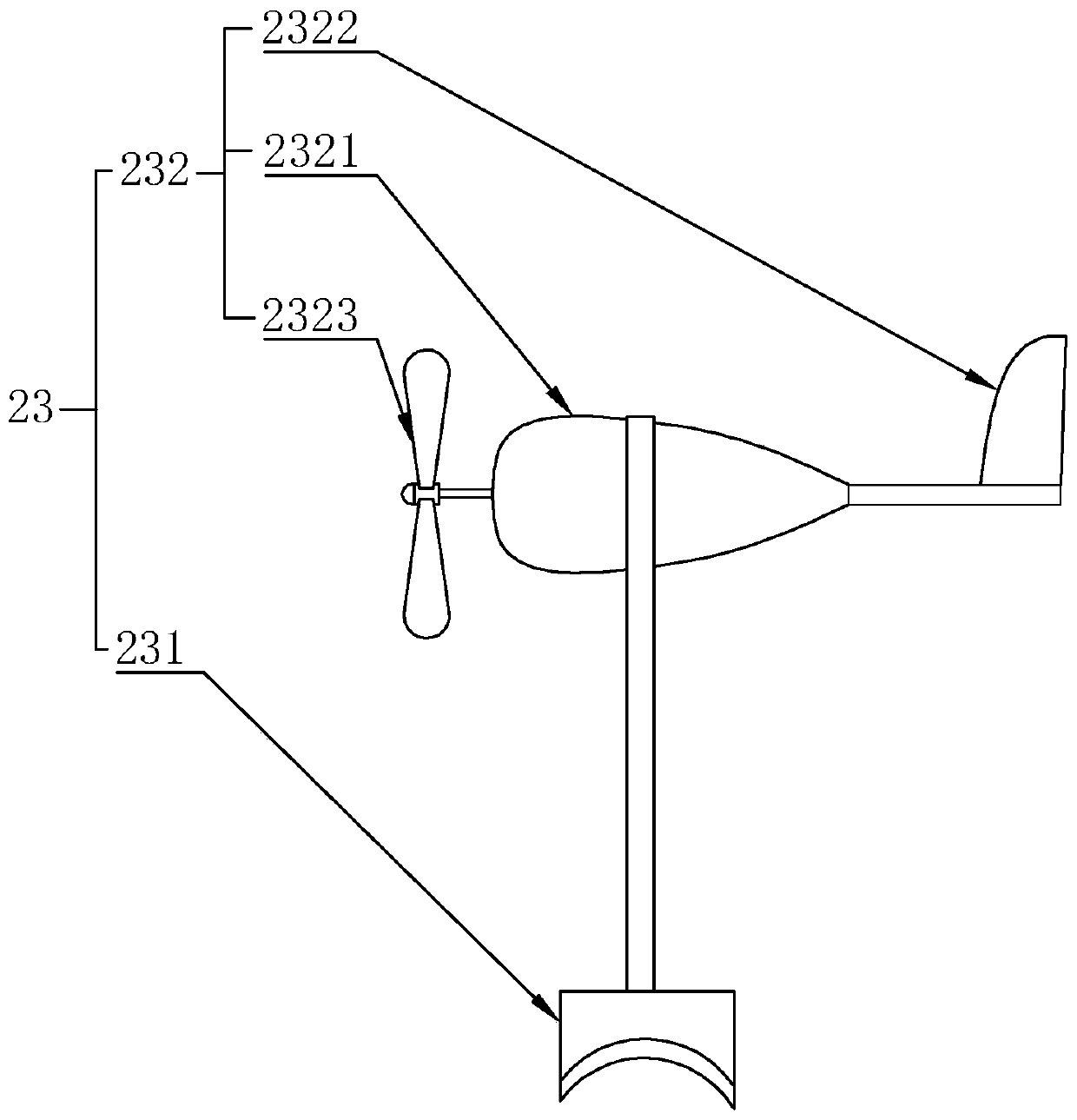
[0021] As an improved specific embodiment, the wind detection device 23 includes a detection base 231 and a detection head 232 fixed on the detection base 231, and the lower side of the detection base 231 is provided with a hook for connecting to the top of the amusement part 22. Velcro, the detection head 232 is fixed on the top of the detection base 231 through a connecting rod, and the detection head 232 is connected to the controller 11 through a wire. Through the setting of the above structure, the detection head can be simply and effectively realized. 232 is detachably installed on the top of the play part 22, so that the castle body 21 can be rolled up during transportation, which greatly facilitates the transportation of the bouncy castle.
[0022] As an improved specific implementation, the detection head 232 includes a detection motor 2321, a paddle tail 2322 and a paddle 2323. The body of the detection motor 2321 is rotatably connected to the upper end of the connect...
Embodiment approach
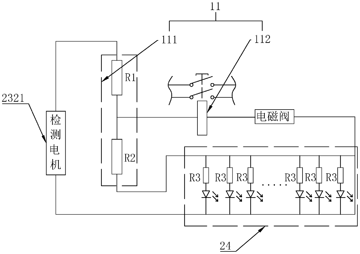
[0026]As an improved specific implementation, the voltage detection circuit 111 includes a resistor R1 and a resistor R2, one end of the resistor R1 is connected to the positive terminal of the detection motor 2321, and the other end is coupled to one end of the resistor R2, the resistor The other end of R2 relative to the resistor R1 is connected to the transfer switch 112 and then connected to the negative terminal of the detection motor 2321, and the other end of the resistor R1 relative to the detection motor 2321 is connected to the alarm light bar 24 and then connected to the negative terminal of the detection motor 2321, Through the setting of the resistor R1 and the resistor R2, it can be combined into a two-stage step-down circuit. After stepping down the output voltage of the detection motor 2321 through the resistor R1, the alarm light bar 24 can be driven to emit light, and the output voltage can be passed through the resistor R1 and the resistor R1. After the resis...
PUM
 Abstract
Description
Claims
Application Information
 - R&D
- Intellectual Property
- Life Sciences
- Materials
- Tech Scout
- Unparalleled Data Quality
- Higher Quality Content
- 60% Fewer Hallucinations
Browse by: Latest US Patents, China's latest patents, Technical Efficacy Thesaurus, Application Domain, Technology Topic, Popular Technical Reports.
© 2025 PatSnap. All rights reserved.Legal|Privacy policy|Modern Slavery Act Transparency Statement|Sitemap|About US| Contact US: help@patsnap.com


