
Method and device for optimizing flowing at junction of leading edge become-warped wing flap and leading edge slat

A technology of leading edge slats and optimization methods, applied in the directions of transportation and packaging, affecting the air flow flowing through the surface of the aircraft, aircraft parts, etc. The problem of wing flow separation and other problems can overcome the adverse flow interference, improve the maximum lift coefficient, and promote practical effects.

Active Publication Date: 2019-12-06
中国航空研究院
View PDF21 Cites 2 Cited by
  • Summary
  • Abstract
  • Description
  • Claims
  • Application Information

AI Technical Summary

Problems solved by technology

However, it was found in the research that at the spanwise junction of the two leading edge flaps, due to the difference in flap type and the discontinuity of the geometric shape, complex flow phenomena will be caused, and at this position when the angle of attack increases Premature separation of flow on the upper surface of the wing
[0004] For aircraft with wing-mounted engine nacelles, the two leading edge flaps can be separated by the design of the engine pylon, but for aircraft with non-wing-mounted engines, it is currently impossible to improve the design of the engine pylon, and it is difficult to effectively solve the two flaps. Flow separation conundrum at the spanwise junction of a leading-edge flap

Method used


Image

  • Method and device for optimizing flowing at junction of leading edge become-warped wing flap and leading edge slat
  • Method and device for optimizing flowing at junction of leading edge become-warped wing flap and leading edge slat
  • Method and device for optimizing flowing at junction of leading edge become-warped wing flap and leading edge slat

Examples


Embodiment 1

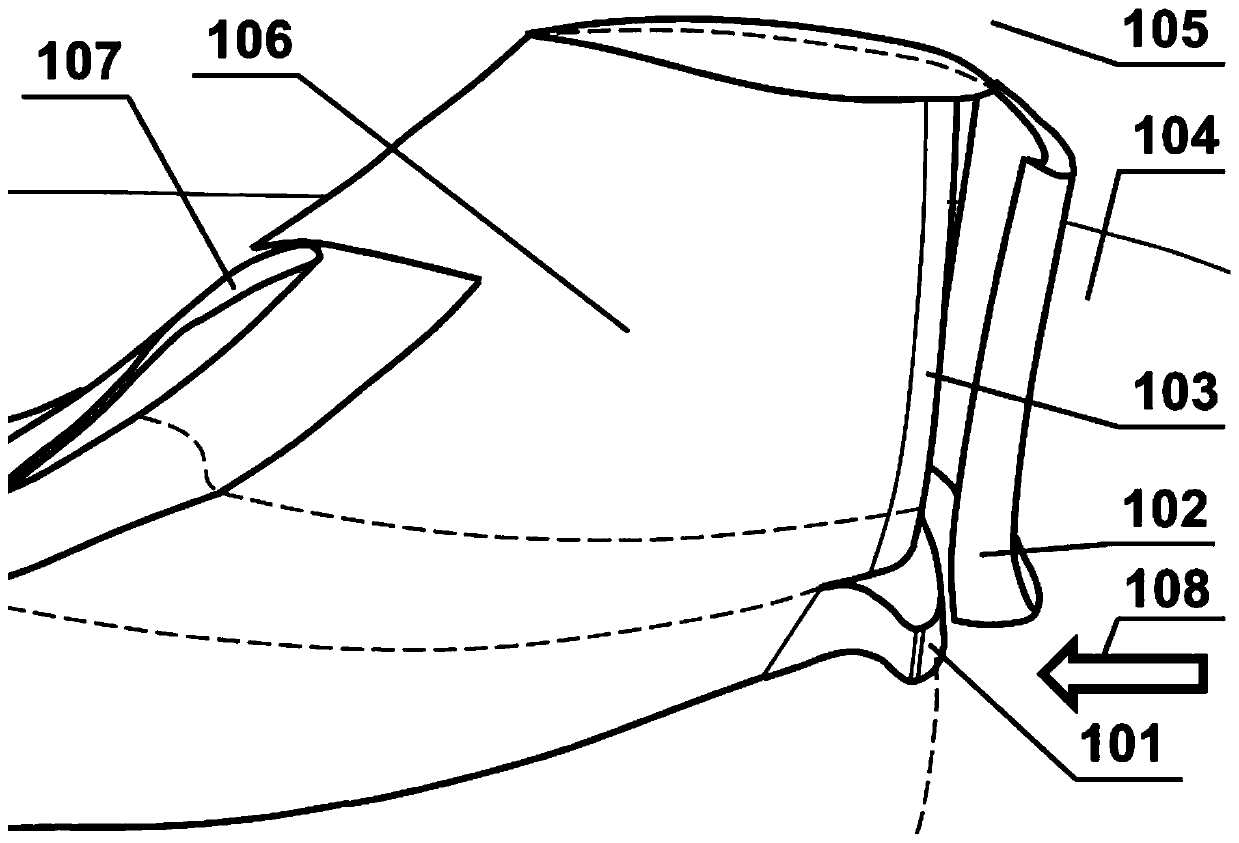
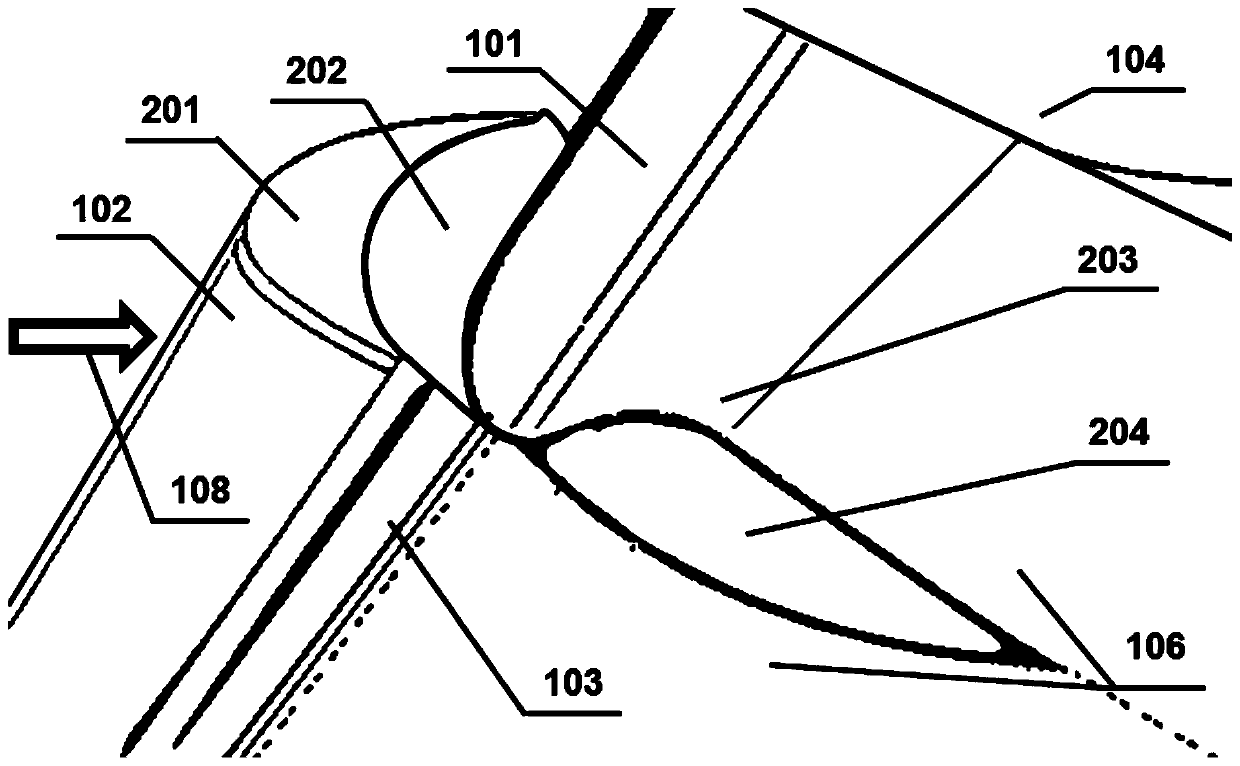
[0046] Example 1, such as Figure 4 As shown: the overall structure of the first flow spacer not only includes the principle shape 202 of the first flow spacer itself, but also includes part of the installation structure, see the overall structure shape 401 Figure 4 The thick and short lines marked in , when the first flow spacer is actually installed, it is fixedly installed on the inner side 201 of the leading edge slat, and is retracted together with the slat. In addition, a slit slightly wider than the first flow spacer is opened on the innermost leading edge fixed section of the leading edge slat and a corresponding seal is applied; when the slat is retracted, the overall structural shape 401 of the first flow spacer will be included If the flow is no longer restrained in the slot, there may be a small arc section exposed on the lower surface of the leading edge of the wing at its lower edge, and this small arc will not have a significant impact on the flow; it can also ...

Embodiment 2

[0047] Example 2, such as Figure 5 As shown: the first flow spacer is the same as the first solution, and it is retracted together with the slat 102, so it will not be repeated. Unlike the solution in the first embodiment, in this embodiment, the second flow spacer is installed on the outer section of the leading-edge curved flap in an integrally fixed manner, and does not follow the sagging of the leading-edge curved flap 101 It can be retracted and moved, and its overall structural shape is 501 such as Figure 5 Indicated by the thick dashed lines in . In addition, the outer side of the second flow spacer is still in parallel contact with the first flow spacer installed on the innermost side of the slat or there is a small gap (for a full-scale aircraft with an average aerodynamic chord of 4.2 meters, the gap is 3 to 5 mm and can be adjusted appropriately. seal). In the flap retracted state, the overall structural shape 501 of the second flow spacer will remain on the lo...


PUM


Abstract

The invention belongs to the technical field of flowing control and provides a method and device for optimizing flowing at the junction of a wing leading edge become-warped wing flap and a leading edge slat of an aviation flying machine and inhibiting and postponing flowing separation of the area. According to the method and device, due to the steps of flow field analyzing, pneumatic design, device installing, a wind tunnel test, result analyzing, relevant adjusting and the like, it is put forwards that in a wing inner side leading edge become-warped wing flap and outer side leading edge slatcombined construction, first flowing isolating pieces and second flowing isolating pieces are arranged. The first flowing isolating pieces are located between the leading edge become-warped wing flapand the leading edge slat, and arranged in the forward stretching direction of the slat; and the second flowing isolating pieces are also located at the junction of the leading edge become-warped wingflap and the leading edge slat, and arranged in the down flow direction of the lower surface of a wing. The flowing optimizing device effectively overcomes the flowing adverse disturbance at the junction of the leading edge become-warped wing flap and the leading edge slat, generation of flowing separation of the upper surface is postponed, and a maximum elevating force coefficient of an airplaneis increased. Besides, the method and device are clear in principle, simple in structure, and remarkable in effect and are verified by the wind tunnel test.

Description

technical field [0001] The invention belongs to the technical field of flow control, and proposes a method and a corresponding device for optimizing the flow at the junction of an aeronautical wing's leading-edge curved flap and a leading-edge slat, and suppressing and delaying flow separation in this area. Background technique [0002] With the higher requirements of green aviation for the design of new-generation aircraft, seamless leading-edge flaps that can reduce aerodynamic noise and optimize surface flow have received increasing attention. Among them, the integral drooping flap at the leading edge, which can simplify the motion mechanism, has been applied on the inner wing of the latest large civil aircraft; , can further maintain the continuous transition of the outer surface of the leading edge, which is more conducive to the realization of laminar flow wing design, so it has become a current research hotspot. [0003] In the practice of the design and research of ...

Claims


Application Information

Patent Timeline
Patent Type & Authority Applications(China)
IPC IPC(8): B64C9/22B64C23/00
CPCB64C9/22B64C23/00
Inventor 钟敏华俊郑遂王浩张国鑫王钢林李小飞李岩孙侠生
Owner 中国航空研究院
Learn More