A method and device for optimizing the flow at the junction of a leading-edge curved flap and a leading-edge slat
A leading edge slat, optimization method technology, applied in the direction of transportation and packaging, affecting the air flow through the surface of the aircraft, aircraft parts, etc., can solve the complex flow, flow separation on the upper surface of the wing, difficult to effectively solve the leading edge flap problems such as the problem of wing flow separation, to achieve the effect of improving the maximum lift coefficient, overcoming the adverse flow interference, and promoting practical application.
- Summary
- Abstract
- Description
- Claims
- Application Information
AI Technical Summary
Problems solved by technology
Method used
Image
Examples
Embodiment 1
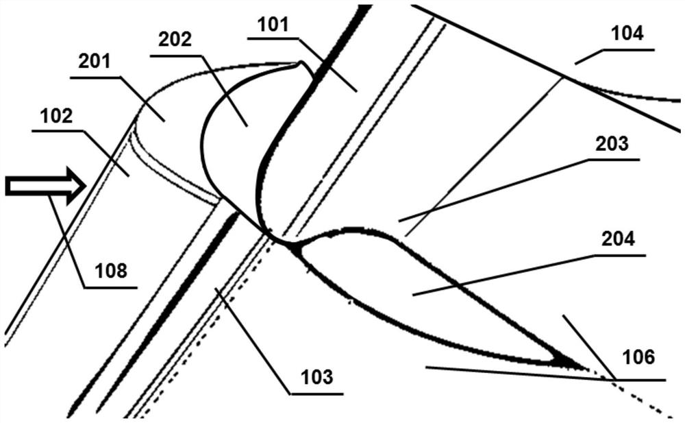
[0046] Example 1, such as Figure 4 As shown: the overall structure of the first flow spacer not only includes the principle shape 202 of the first flow spacer itself, but also includes part of the installation structure, see the overall structure shape 401 Figure 4 The thick and short lines marked in , when the first flow spacer is actually installed, it is fixedly installed on the inner side 201 of the leading edge slat, and is retracted together with the slat. In addition, a slit slightly wider than the first flow spacer is opened on the innermost leading edge fixed section of the leading edge slat and a corresponding seal is applied; when the slat is retracted, the overall structural shape 401 of the first flow spacer will be included If the flow is no longer restrained in the slot, there may be a small arc section exposed on the lower surface of the leading edge of the wing at its lower edge, and this small arc will not have a significant impact on the flow; it can also ...
Embodiment 2
[0047] Example 2, such as Figure 5 As shown: the first flow spacer is the same as the first solution, and it is retracted together with the slat 102, so it will not be repeated. Unlike the solution in the first embodiment, in this embodiment, the second flow spacer is installed on the outer section of the leading-edge curved flap in an integrally fixed manner, and does not follow the sagging of the leading-edge curved flap 101 It can be retracted and moved, and its overall structural shape is 501 such as Figure 5 Indicated by the thick dashed lines in . In addition, the outer side of the second flow spacer is still in parallel contact with the first flow spacer installed on the innermost side of the slat or there is a small gap (for a full-scale aircraft with an average aerodynamic chord of 4.2 meters, the gap is 3 to 5 mm and can be adjusted appropriately. seal). In the flap retracted state, the overall structural shape 501 of the second flow spacer will remain on the lo...
PUM
 Abstract
Description
Claims
Application Information
 - R&D
- Intellectual Property
- Life Sciences
- Materials
- Tech Scout
- Unparalleled Data Quality
- Higher Quality Content
- 60% Fewer Hallucinations
Browse by: Latest US Patents, China's latest patents, Technical Efficacy Thesaurus, Application Domain, Technology Topic, Popular Technical Reports.
© 2025 PatSnap. All rights reserved.Legal|Privacy policy|Modern Slavery Act Transparency Statement|Sitemap|About US| Contact US: help@patsnap.com


