Three-phase integrated GIS independent bus voltage measuring device

A technology for measuring device and bus voltage, applied in the field of power system, can solve the problems of large size, poor accuracy and high cost of voltage transformers, and achieve the effects of eliminating mutual interference, ensuring accuracy and low cost

Active Publication Date: 2019-12-06
NORTH CHINA ELECTRIC POWER UNIV (BAODING)
View PDF10 Cites 4 Cited by
  • Summary
  • Abstract
  • Description
  • Claims
  • Application Information

AI Technical Summary

Problems solved by technology

[0002] With the sharp increase in demand for electricity, the scale of the power grid continues to grow, the voltage level of the power system continues to increase, and the structure of the power grid becomes more intricate, which increases the difficulty of real-time monitoring of the operating status of the power system and the maintenance of power equipment.
However, most of the high-voltage measurement methods and high-voltage measurement equipment currently used are voltage transformers with transformers as their essence. There are many problems in practical applications. For example, electromagnetic voltage transformers will appear ferromagnetic at higher voltages Saturation, nonlinear output voltage, poor transient response, etc., and there is a risk of flammability and explosion; capacitive voltage transformers have many components and complex structures, and must be used in conjunction with small-capacity electromagnetic voltage transformers, and are subject to temperature and frequency have great influence, and the accuracy is po

Method used


Image

  • Three-phase integrated GIS independent bus voltage measuring device
  • Three-phase integrated GIS independent bus voltage measuring device
  • Three-phase integrated GIS independent bus voltage measuring device

Examples


Embodiment Construction

[0025] The following will clearly and completely describe the technical solutions in the embodiments of the present invention with reference to the accompanying drawings in the embodiments of the present invention. Obviously, the described embodiments are only some, not all, embodiments of the present invention. Based on the embodiments of the present invention, all other embodiments obtained by persons of ordinary skill in the art without making creative efforts belong to the protection scope of the present invention.

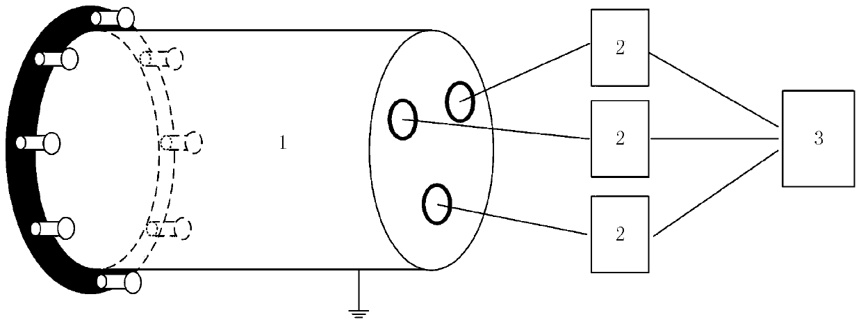
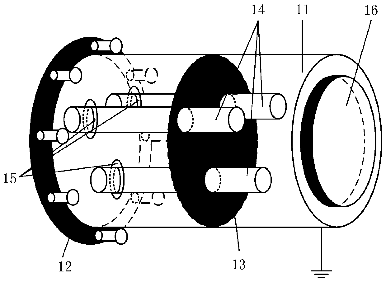
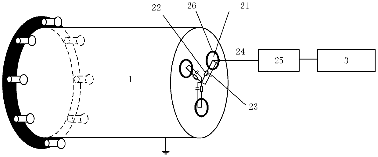
[0026] The purpose of the present invention is to provide a three-phase integrated GIS independent bus voltage measurement device, which can be tested and calibrated before being put into use, to ensure the accuracy of voltage measurement, and is easy to maintain and meet the practical application.

[0027] In order to make the above objects, features and advantages of the present invention more comprehensible, the present invention will be further described in...


PUM

PropertyMeasurementUnit
Resistanceaaaaaaaaaa

Abstract

The invention discloses a three-phase integrated GIS independent bus voltage measuring device and relates to the technical field of power systems. The device comprises a secondary measurement module as well as a measuring device body and a voltage display module which are connected with the secondary measurement module, and the voltage display module is used for calculating and displaying bus voltages of high-voltage conductors; the measuring device body comprises a measuring tank body, a connecting flange, a bus connector, a metal shielding case and three high-voltage conductors; the measuring tank body comprises an open end and a closed end; the connecting flange is a metal connecting part mounted at the open end, and the connecting flange is used for connecting the measuring tank body and a GIS tank body, so that the bus voltage measuring device and the GIS tank body are mutually independent; the bus connector is mounted on the high-voltage conductors, the bus connector is connectedwith the high-voltage conductors and a bus of the GIS tank body during normal operation, and the bus connector is connected with the high-voltage conductors and a three-phase voltage source during calibration, thus the aim that detection and the calibraction can be performed before the device comes into use is achieved, and voltage measurement accuracy is guaranteed.

Description

technical field [0001] The invention relates to the technical field of power systems, in particular to a three-phase integrated GIS independent bus voltage measurement device. Background technique [0002] With the sharp increase in electricity demand, the scale of the power grid continues to grow, the voltage level of the power system continues to increase, and the structure of the power grid becomes more intricate, which increases the difficulty of real-time monitoring of the operating status of the power system and the maintenance of power equipment. However, most of the high-voltage measurement methods and high-voltage measurement equipment currently used are voltage transformers with transformers as their essence. There are many problems in practical applications. For example, electromagnetic voltage transformers will appear ferromagnetic at higher voltages Saturation, nonlinear output voltage, poor transient response, etc., and there is a risk of flammability and explo...

Claims


Application Information

Patent Timeline
IPC IPC(8): G01R19/00G01R1/04G01R35/00
CPCG01R1/0416G01R19/0084G01R35/005
Inventor 卢斌先李瑞宋丽娟
Owner NORTH CHINA ELECTRIC POWER UNIV (BAODING)
Why Eureka
Try Eureka