
A mobile display stand for architectural design

A technology for architectural design and display stands, applied in display stands, display hangers, display shelves, etc., can solve problems such as poor adjustment and inability to achieve display effects, and achieve improved display effects, convenient observation and learning, and flexible display operations Effect

Active Publication Date: 2020-08-21
中原工学院信息商务学院
View PDF1 Cites 0 Cited by
  • Summary
  • Abstract
  • Description
  • Claims
  • Application Information

AI Technical Summary

Problems solved by technology

Although the device can display the architectural model of the architectural design, its adjustment is poor and cannot achieve a comprehensive display effect. Therefore, a mobile architectural design display stand is now provided to solve the above technical problems

Method used


Image

  • A mobile display stand for architectural design
  • A mobile display stand for architectural design
  • A mobile display stand for architectural design

Examples


Embodiment 1

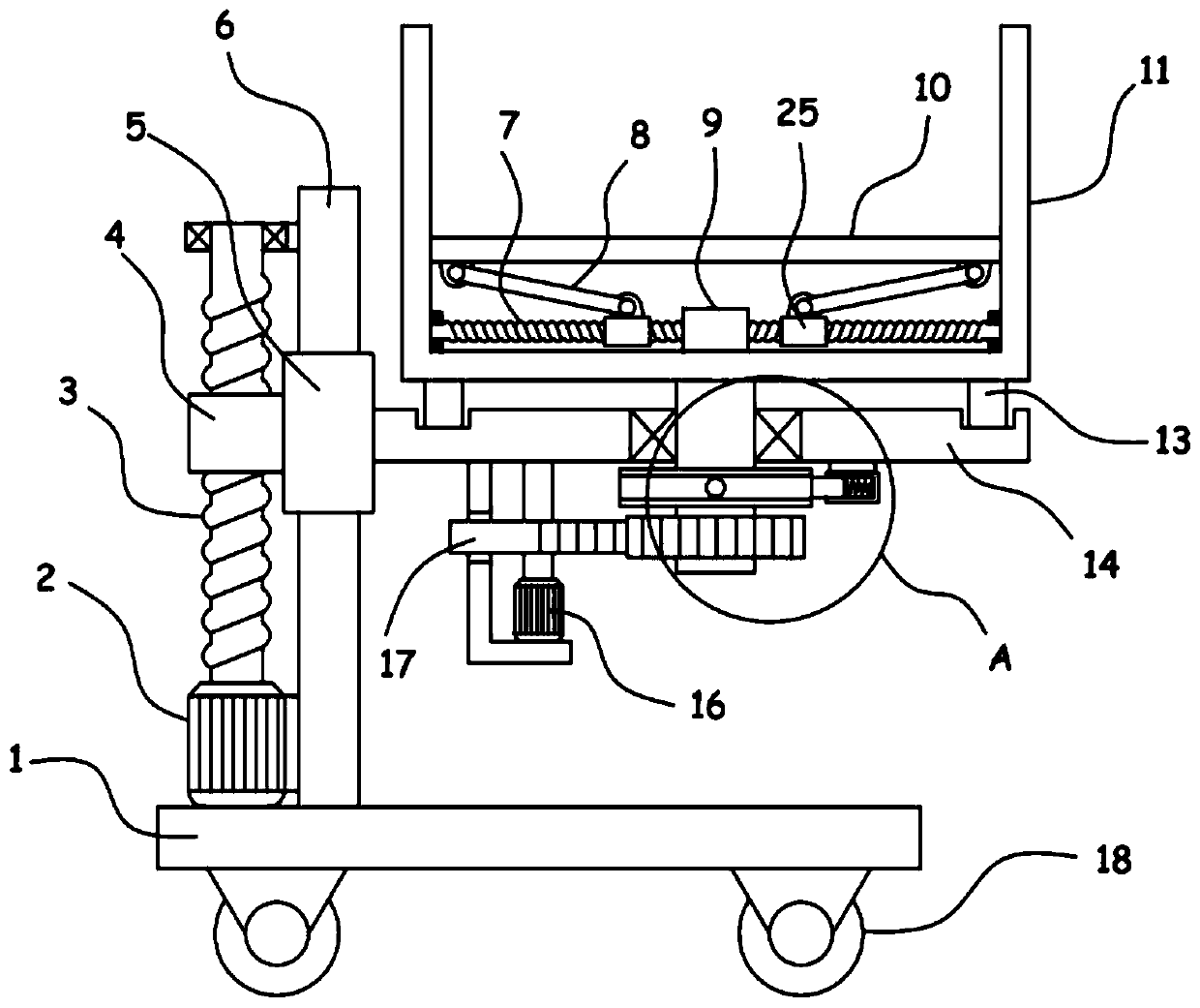
[0021] see Figure 1-3 , a mobile display stand for architectural design, comprising a support platform 1, the bottom of the support platform 1 is rotatably equipped with traveling wheels 18, a column 6 is vertically fixed on the support platform 1, and a vertical sliding sleeve on the column 6 is provided with a drive through a height adjustment mechanism. The sliding sleeve 5, the side wall of the sliding sleeve 5 is fixed with a support plate 14, a steering shaft 24 driven by a steering mechanism is vertically pivoted on the support plate 14, the upper end of the steering shaft 24 is fixed with a placement basket 11, and the placement basket 11 passes The lifting mechanism is drivingly connected with a bearing plate 10 for bearing the architectural model.

[0022] The device can realize the movement of the position through the walking wheels 18. The architectural model of the architectural design is accommodated by placing the basket 11, and the loading plate 10 in the plac...

Embodiment 2

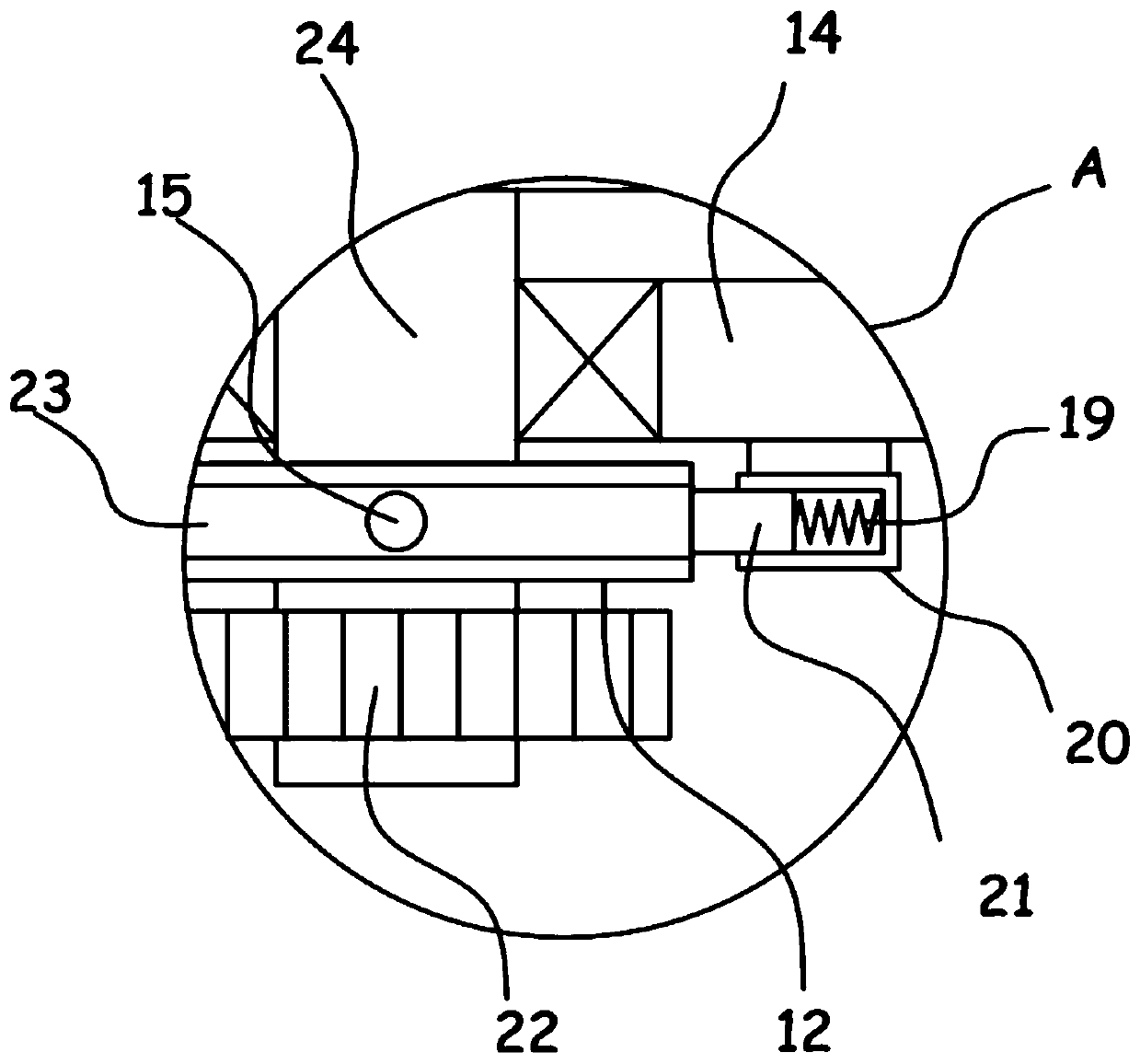
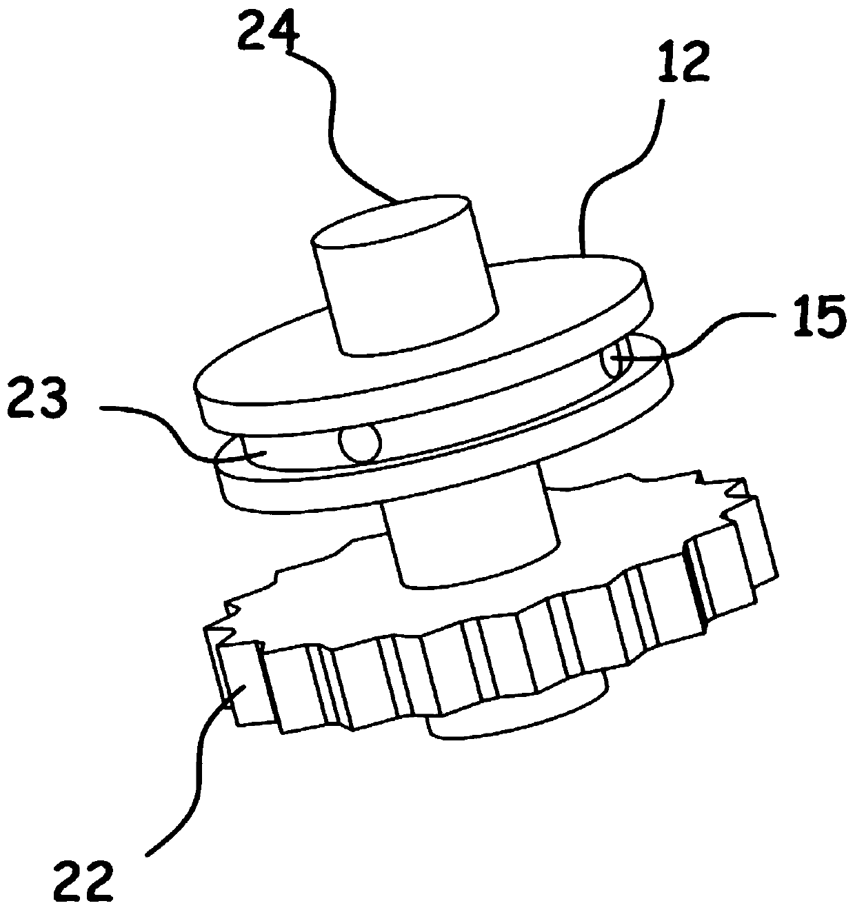
[0027] In order to ensure the stability of the steering mechanism during the steering adjustment of the architectural model, on the basis of Embodiment 1, in addition, the steering shaft 24 is sleeved and fixed with a positioning disc 12, and the surface of the positioning disc 12 is circumferentially provided with an annular groove 23 for positioning. There are several arc grooves 15 evenly distributed in the annular groove 23 in the disk 12. The bottom of the support plate 14 is provided with inserting posts 21 that are elastically engaged with the arc grooves 15. The bottom of the support plate 14 is fixed with a sleeve 20. The column 21 is slidably installed in the sleeve 20 , and an abutment spring 19 is fixedly connected between the inserted column 21 and the sleeve 20 .

[0028] Through the above arrangement, when the transmission gear 22 and the incomplete gear 17 are meshed for transmission, the insertion post 21 slides along the annular groove 23, and when the transmi...


PUM


Abstract

The invention discloses a mobile display table for building design, and relates to the technical field of building design. The mobile display table comprises a supporting table, wherein walking wheelsare rotationally installed at the bottom of the supporting table; a sliding sleeve pipe driven by a height adjusting mechanism is vertically arranged on a stand column in a sliding mode; a containingbasket is fixed at the upper end of a steering shaft; and a bearing plate used for bearing a building model is in driving connection in the containing basket through a lifting mechanism. According tothe mobile display table, the building model designed by the building is stored through the containing basket; the lifting mechanism can drive the bearing plate to ascend and descend to achieve storage and extension of the building model out of the containing basket, so that the display operation of the building model is more flexible; an arranged steering mechanism can drive the containing basket to carry out automatic intermittent rotation through the steering shaft, so that the building model on the bearing plate can realize automatic rotary display; and meanwhile, the rotation intermittent period exists in the rotation process, so that a visitor can observe and study conveniently and carefully, and the display effect of the building design is greatly improved.

Description

technical field [0001] The invention relates to the technical field of architectural design, in particular to a mobile display stand for architectural design. Background technique [0002] Architectural design means that before the construction of a building, the designer, according to the construction task, makes a comprehensive assumption in advance of the problems that exist or may occur during the construction process and use process, and draws up the methods and plans to solve these problems. Drawings and documents express it. The product model in the architectural design needs the help of a display stand to facilitate the comprehensive display of the architectural design content. [0003] The patent application publication number is CN107252218 A discloses a mobile display platform for architectural design, including a base, a lifting mechanism is vertically arranged on the base, a placing platform is arranged on the top of the lifting mechanism, and a bottom outer wa...

Claims


Application Information

Patent Timeline
Patent Type & Authority Patents(China)
IPC IPC(8): A47F5/025A47F5/06A47F7/00
CPCA47F5/025A47F5/06A47F7/00
Inventor 马楠秦楠蒲娟胡静李莎莎
Owner 中原工学院信息商务学院
Learn More