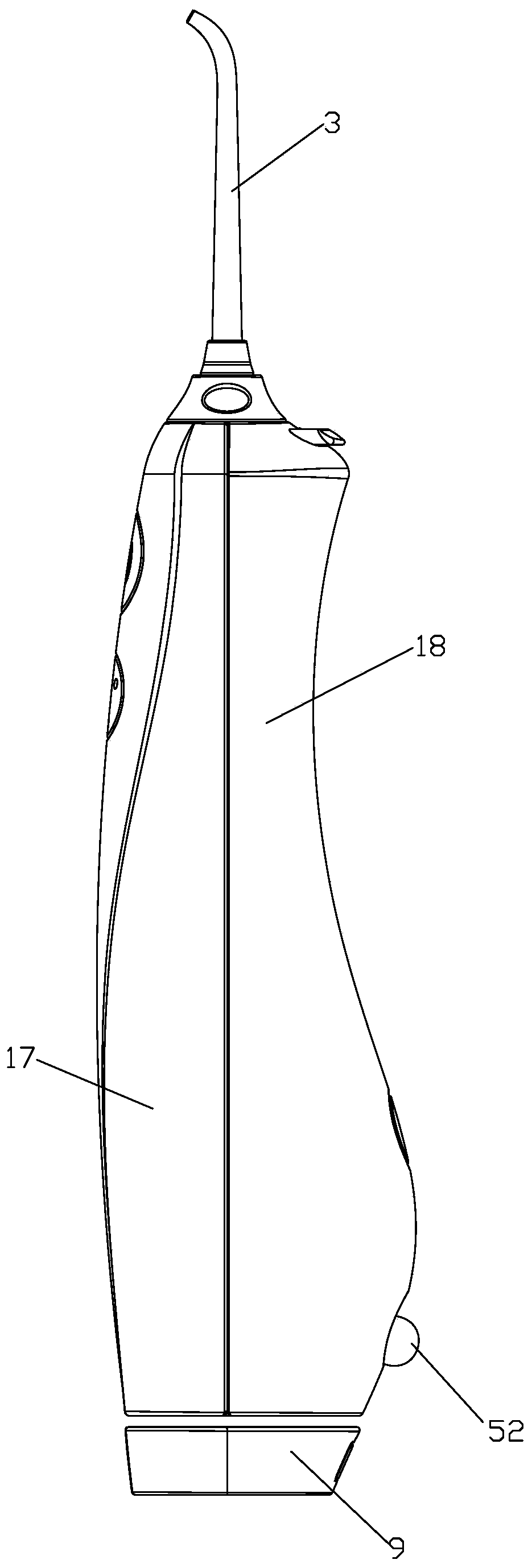
Oral irrigator
A dental flosser and dental flossing technology, applied in dentistry, teeth cleaning, gum massage, etc., can solve the problems of limited use space, easy loss of telescopic tubes, inconvenient portability, etc., and achieve a wide range of use occasions, neat winding, and convenience carrying effect
- Summary
- Abstract
- Description
- Claims
- Application Information
AI Technical Summary
Problems solved by technology
Method used
Image
Examples
Embodiment 1
[0078] see Figure 1 to Figure 13 , The dental flosser includes a housing 1, a dental flossing part 2, a faucet part 3, a winding mechanism 4 and a water pipe 5 capable of bending and winding. The flossing part 2 is fixedly installed in the housing 1 and has a water inlet (first water receiving port) and a water outlet (second water receiving port), the water nozzle part 3 is fixedly installed in the housing 1 and connected The water outlet of the part 2, the tooth flushing part 2 and the faucet part 3 can refer to the prior art, and will not be further described here. According to the needs, the faucet part and the housing can form a connection structure that can be assembled and disassembled. After connecting, the faucet part can be rotated 360° relative to the housing; if necessary, the dental flosser can be adjusted in three gears of high frequency, medium frequency and low frequency. The water pipe 5 is, for example, a water pipe made of flexible material or a corrugated...
Embodiment 2
[0090] see Figure 14 to Figure 18 , it differs from Example 1 in that:
[0091] The anti-rotation mechanism 8 includes a chute 81 and a movable ball 82 recessed on the top surface of the fixed plate 121. The movable ball 82 is a steel ball, and the movable ball 82 can be movably connected in the chute 81 along the chute 81. The movable ball 82 at least partly protrudes from the notch of the chute 81; the lower end of the drum 45 is fixed with a track plate 47, which replaces the baffle plate 452 of the first embodiment to form the lower wall of the accommodating tank 44; The bottom surface of the track plate 47 is concavely provided with a fitting groove 83 for fitting the ball 82. The fitting groove 83 includes an outer ring track 831, an inner ring track 832 and an anti-rotation position 833. The anti-rotation position 833 is interposed between the outer ring track 831 and the inner Between the ring track 832, a first communication groove 834 is provided between the anti-r...
Embodiment 3
[0094] see Figure 19 to Figure 21 , it differs from Embodiment 1 in that: it also includes a motor 10, the motor 10 is installed in the placement space 11 and the power output shaft 101 of the motor 10 and the separator 46 are adapted to pass through the power output shaft 101 of the motor 10 Drive the rotating part 4 to rotate. For example, the PTO shaft 101 is provided with a non-circular structure, and the partition 46 is provided with a perforation adapted to the PTO shaft. The PTO shaft and the partition form a synchronous rotation connection relationship. Wherein the pipe collection is realized by motor drive, specifically: (1), pipe discharge operation: hold the water pipe by hand, make the rotating part 4 rotate, and the water pipe is pulled out; (2), pipe collection operation: press the pipe collection button with your hand , start the motor, and the motor retracts the water pipe. According to requirements, a clutch can also be set between the power output shaft and...
PUM
 Abstract
Description
Claims
Application Information
 - R&D
- Intellectual Property
- Life Sciences
- Materials
- Tech Scout
- Unparalleled Data Quality
- Higher Quality Content
- 60% Fewer Hallucinations
Browse by: Latest US Patents, China's latest patents, Technical Efficacy Thesaurus, Application Domain, Technology Topic, Popular Technical Reports.
© 2025 PatSnap. All rights reserved.Legal|Privacy policy|Modern Slavery Act Transparency Statement|Sitemap|About US| Contact US: help@patsnap.com


