Warp-direction winding inspecting machine

A roll inspection machine and warp technology, which is applied in the inspection of winding strips, textile materials, textiles and paper making, etc., can solve the problems of low efficiency of paper tube change, affecting the efficiency of cloth winding, and laborious handling by workers.

Active Publication Date: 2020-07-07
杭州高氏箱包布业有限公司
View PDF6 Cites 1 Cited by
  • Summary
  • Abstract
  • Description
  • Claims
  • Application Information

AI Technical Summary

Problems solved by technology

[0004] However, whenever a paper tube full of cloth needs to be unloaded, it needs at least two workers to work together to carry it off the two sets of drive rollers, and then place a new paper tube on the two sets of drive rollers. The location is relatively high, and the paper tube full of fabric is heavy, so the workers' handling is quite laborious, and the efficiency of changing the material of the paper tube is relatively low, which affects the winding efficiency of the fabric, so it needs to be improved

Method used


Image

  • Warp-direction winding inspecting machine
  • Warp-direction winding inspecting machine
  • Warp-direction winding inspecting machine

Examples


Embodiment Construction

[0040] The present invention will be described in further detail below in conjunction with the accompanying drawings.

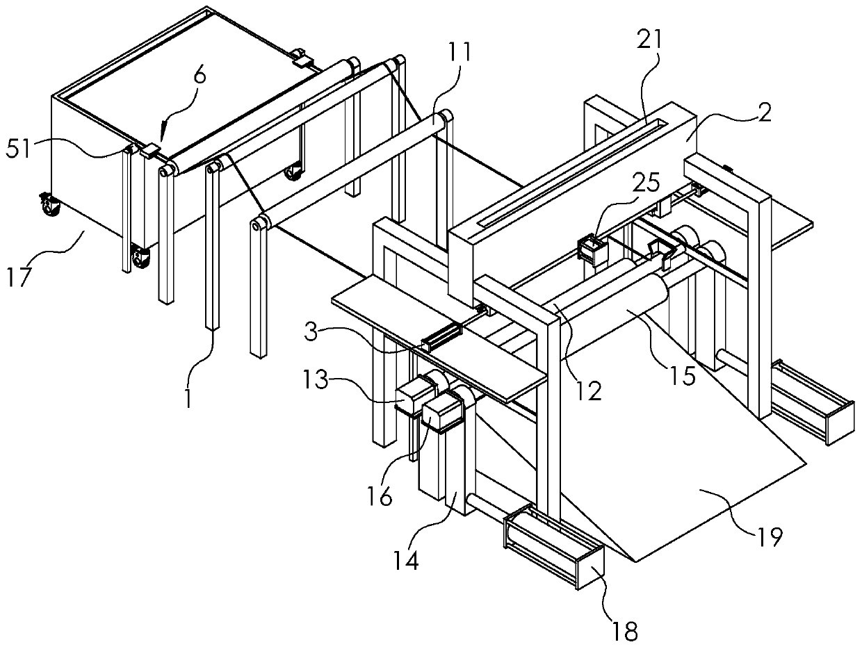
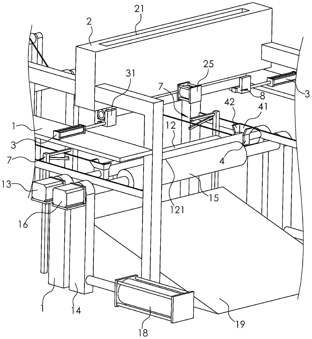
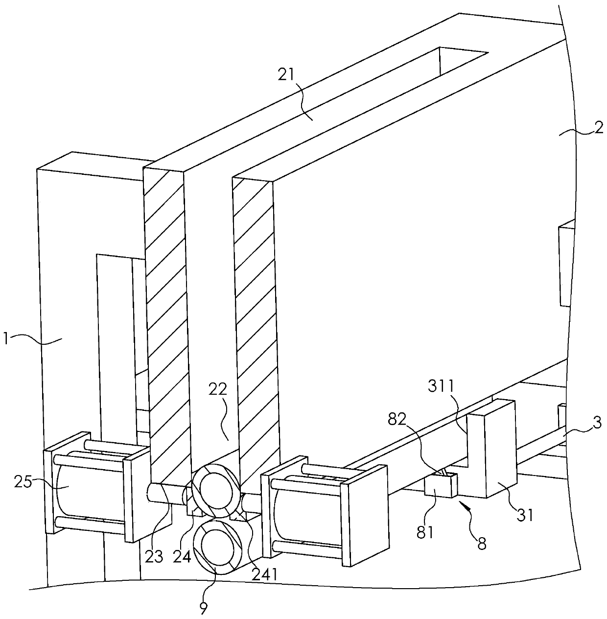
[0041] Such as figure 1 and figure 2 As shown, a warp direction rolling inspection machine includes a frame 1, several cloth guide rollers 11, a driving roller 12, a driving motor 13, a moving frame 14, a rotating roller 15 and a rotating motor 16; The feeding area 17 where the cloth cart is placed; the drive roller 12 and all cloth guide rollers 11 are rotatably connected to the frame 1; the drive motor 13 is fixed on the frame 1, and the output shaft of the drive motor 13 is fixedly connected to the drive roller 12; The roller 15 is rotatably connected to the moving frame 14 and is spaced apart from the driving roller 12. The paper tube 9 for cloth winding is placed on the driving roller 12 and the rotating roller 15; the rotating motor 16 is fixed on the moving frame 14, and the rotating motor 16 The output shaft is fixedly connected to the rotating rol...


PUM


Abstract

The invention relates to a warp-direction winding inspecting machine. The warp-direction winding inspecting machine comprises a machine frame, a plurality of cloth guiding rollers, a driving roller and a driving motor. An output shaft of the driving motor is fixedly connected to the driving roller. The machine frame is provided with a moving frame and a pushing part, and the moving frame is provided with a rotating roller and a rotating motor. When the pushing part drives the moving frame to be away from the driving roller, a falling cavity is formed by enclosing the driving roller and the rotating roller; and the machine frame is further provided with a storage box, a feeding inlet and a discharging outlet are separately formed in the upper side and the lower side of the storage box, thestorage box is further provided with a closing plate and a driving part. When a paper cylinder wound with cloth needs to be discharged, firstly the moving frame is driven to move through the pushing part, so that the paper cylinder wound with the cloth falls from the falling cavity to the lower part; then the moving frame is driven to move and reset through the pushing part, and the driving part drives a closing plate to move, so that the paper cylinder is discharged through the discharging outlet; and the paper cylinder located on the lowermost side of inside of the storage box moves throughthe closing plate and falls onto the driving roller and the rotating roller. The winding efficiency of the cloth is greatly improved.

Description

technical field [0001] The invention relates to the technical field of cloth processing equipment, in particular to a warp direction rolling inspection machine. Background technique [0002] In the textile industry, after the cloth inspection is completed, the cloth usually needs to be folded onto the cloth drop car by a swing machine, and then the worker pushes the cloth fall car to the warp rolling inspection machine, and the warp direction rolling inspection machine will check the cloth Winding rolls for subsequent packaging and delivery of the fabric. [0003] The existing meridional rolling inspection machine includes a frame, several cloth guide rollers rotatably connected to the frame, two sets of driving rollers rotatably connected to the frame, and a drive motor fixed on the frame. The output shaft of the drive motor is fixedly connected to the frame. on one of the drive rollers. In the process of fabric rewinding, the paper roll for fabric winding is first placed...

Claims


Application Information

Patent Timeline
Patent Type & Authority Applications(China)
IPC IPC(8): B65H19/30B65H20/02B65H18/10B05C1/02B05C11/10B05C13/02
CPCB05C1/02B05C11/10B05C13/02B65H18/10B65H19/30B65H20/02D06H3/00D06H7/00
Inventor 高香丹周辉
Owner 杭州高氏箱包布业有限公司
Why Eureka
Try Eureka