Deep-cavity screw locking device

A locking device and screw technology, which is applied in the field of screw locking, can solve the problems such as the screw fastening process meets the requirements, fails to meet the mass production requirements, poor quality consistency, etc., and realizes screw assembly automation, reduces interference, and increases positioning effect of means

Inactive Publication Date: 2019-12-10
CHINA ELECTRONIC TECH GRP CORP NO 38 RES INST +1
View PDF16 Cites 1 Cited by
  • Summary
  • Abstract
  • Description
  • Claims
  • Application Information

AI Technical Summary

Problems solved by technology

With the development of science and technology, the integration of products is getting higher and higher, especially in 3C, automotive electronics and other products, there are a large number of narrow deep cavity structures, and the screw fastening process of this part cannot meet the requirements through traditional automation mechanisms. At present, most of them are assembled manually, the assembly efficiency is low, the quality consistency is poor, and it cannot meet the requirements of mass production

Method used


Image

  • Deep-cavity screw locking device
  • Deep-cavity screw locking device
  • Deep-cavity screw locking device

Examples


Embodiment Construction

[0022] The above and other technical features and advantages of the present invention will be described in more detail below in conjunction with the accompanying drawings.

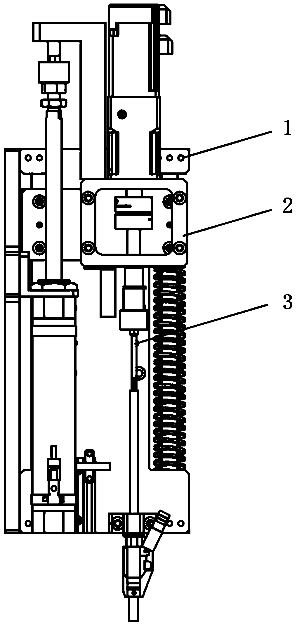
[0023] Such as figure 1 as shown, figure 1 It is a structural view of the deep cavity screw locking device; the deep cavity screw locking device includes a main movement assembly 1, a locking assembly 2 and a support assembly 3, and the main movement assembly 1 is arranged on the support assembly 3 , the main movement assembly 1 is connected to the locking assembly 2, and the main movement assembly 1 drives the locking assembly 2 to achieve linear displacement, thereby ensuring that the locking components on the locking assembly 2 move to a deep The specified position of the cavity, the locking assembly 2 realizes the rotation and locking operation of the screw.

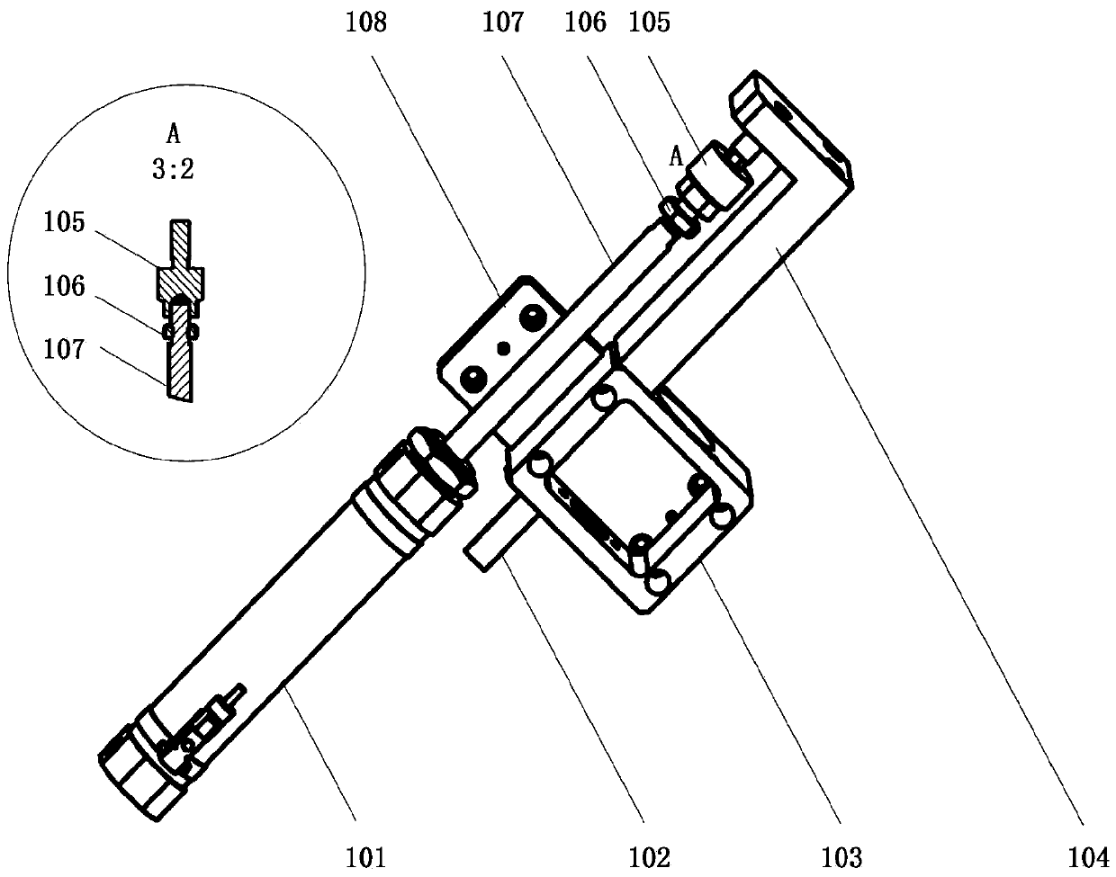
[0024] Such as figure 2 as shown, figure 2 It is a structural view of the main motion assembly; the main motion assembly 1 includes a cyli...


PUM


Abstract

The invention discloses a deep-cavity screw locking device, which includes a main moving assembly, a locking assembly and a supporting assembly. The main moving assembly is arranged on the supportingassembly, the main moving assembly is connected with the locking assembly, the main moving assembly drives the locking assembly to achieve linear displacement, and the locking assembly realizes rotation locking operation of screws. According to the deep-cavity screw locking device, an electromagnetic material is innovatively combined with a screw locking mechanism, the interference of screw locking is effectively reduced without adding other accessories, and automation of screw mounting in a deep cavity or a narrow cavity is realized.

Description

technical field [0001] The invention relates to the technical field of screw locking, in particular to a deep cavity screw locking device. Background technique [0002] Threaded connection is a connection form widely used in engineering. For the automation of screw fastening process, there are a large number of standardized equipment on the market, but due to the interference of its own locking mechanism, most of them can only be applied to open and unobstructed locking positions. . With the development of science and technology, the integration of products is getting higher and higher, especially in 3C, automotive electronics and other products, there are a large number of narrow deep cavity structures, and the screw fastening process of this part cannot meet the requirements through traditional automation mechanisms. At present, most of them are assembled manually, with low assembly efficiency and poor quality consistency, which cannot meet the requirements of mass produc...

Claims


Application Information

Patent Timeline
Patent Type & Authority Applications(China)
IPC IPC(8): B23P19/06
CPCB23P19/006B23P19/06
Inventor 蔡若凡武斌功柳龙华陈桥肖龙张源晋
Owner CHINA ELECTRONIC TECH GRP CORP NO 38 RES INST
Why Eureka
Try Eureka