Rotary disc and rotary core integrated structure for injection molding

A rotary table and rotary center technology is applied in the field of integrated structure of rotary table and rotary center for injection molding, which can solve problems such as affecting the efficiency of injection molding processing, single function of rotary table device, and high price of injection molding machine, saving space and resources, Simple structure and the effect of reducing processing cost

Inactive Publication Date: 2019-12-10
徐宇
View PDF2 Cites 0 Cited by
  • Summary
  • Abstract
  • Description
  • Claims
  • Application Information

AI Technical Summary

Problems solved by technology

[0002] Injection molding machines are generally used for injection molding of household kitchen products. Since the turntable device on the injection molding machine can rotate, the mold can be mounted on the turntable device to perform product molding processing. CN203236662U, US4950350(A), CN101778708A, CN102873815A, CN103213241A disclosed patent documents injection molding machine turntable device can complete product molding processing, but the turntable device function of these injection molding machines is relatively single, using the above-mentioned type of injection molding machine to inject a variety of products It is necessary to continuously replace multiple injection molding machines to complete, which seriously affects the efficiency of injection molding processing. At the same time, due to the relatively expensive price of injection molding machines, one machine can range from hundreds of thousands to more than one million, resulting in injection molding processing. The factory needs to invest a lot of costs to operate normally

Method used


Image

  • Rotary disc and rotary core integrated structure for injection molding
  • Rotary disc and rotary core integrated structure for injection molding
  • Rotary disc and rotary core integrated structure for injection molding

Examples


Embodiment Construction

[0024] It should be noted that, in the case of no conflict. The features in the embodiments and implementations of the present invention can be combined with each other. The present invention will be described in detail below with reference to the accompanying drawings and examples.

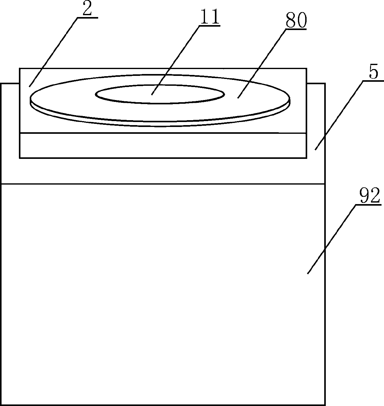
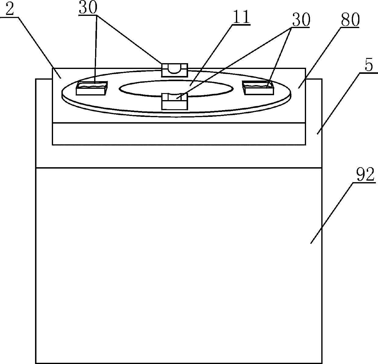
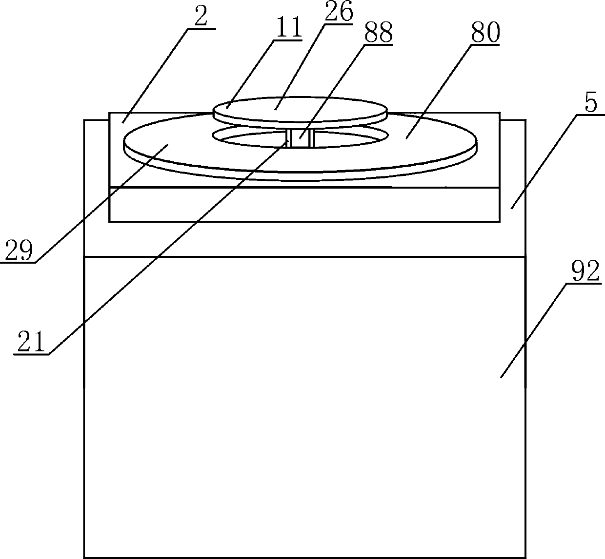
[0025] as attached figure 1 , attached figure 2 , attached image 3 , attached Figure 4 , attached Figure 5 , attached Figure 6 , attached Figure 7 , attached Figure 8 , attached Figure 9 , attached Figure 10 As shown, the present invention provides a turntable and center integrated structure for injection molding, which includes an organic base 92, a mounting plate 2, a turntable device 80 and a turntable device 11 arranged on the turntable device, the turntable The device is installed on the machine base and can rotate 360 ​​degrees forward or reverse, and the rotating center device is installed on the turntable device, which can rotate 360 ​​degrees forward or reverse and can...


PUM


Abstract

The invention provides a rotary disc and rotary core integrated structure for injection molding. The rotary disc and rotary core integrated structure comprises a machine base, a mounting plate, a rotary disc device and a rotary core device. The periphery of the mounting plate is square, a first round hole is formed in the middle of the mounting plate, and the mounting plate is mounted on the machine base. The rotary disc device is mounted in the first round hole and can rotate by 360 degrees back and forth, a second round hole is formed in the rotary disc device, and the rotary core device ismounted in the second round hole, can rotate by 360 degrees back and forth and can move up and down. By the adoption of the structure, the rotary disc and rotary core integrated structure has the beneficial effects that the rotary core device is arranged on the rotary disc device, the rotary disc device can machine products without workpieces, the rotary core devices can machine products with theworkpieces, primary injection molding and secondary injection molding can be simultaneously carried out regardless of various large and small products, and the use integration effect of a multi-purpose injection molding machine is achieved.

Description

technical field [0001] The invention relates to an integrated structure of a rotating disk and a rotating center for injection molding. Background technique [0002] Injection molding machines are generally used for injection molding of household kitchen products. Since the turntable device on the injection molding machine can rotate, the mold can be mounted on the turntable device to perform product molding processing. CN203236662U, US4950350(A), CN101778708A, CN102873815A, CN103213241A disclosed patent documents injection molding machine turntable device can complete product molding processing, but the turntable device function of these injection molding machines is relatively single, using the above-mentioned type of injection molding machine to inject a variety of products It is necessary to continuously replace multiple injection molding machines to complete, which seriously affects the efficiency of injection molding processing. At the same time, due to the relatively ...

Claims


Application Information

Patent Timeline
Patent Type & Authority Applications(China)
IPC IPC(8): B29C45/06B29C45/17
CPCB29C45/06B29C45/1742
Inventor 徐宇
Owner 徐宇
Why Eureka
Try Eureka