

Method for eliminating delay effect of self-powered neutron detector based on digital circuit
A neutron detector, self-sufficient energy technology, applied in the direction of neutron radiation measurement, instruments, measuring devices, etc., can solve problems that are difficult to understand, the role cannot be ignored, and the Laplace transform method is complicated
Active Publication Date: 2019-12-10
XI AN JIAOTONG UNIV
View PDF8 Cites 0 Cited by
- Summary
- Abstract
- Description
- Claims
- Application Information
AI Technical Summary
Problems solved by technology
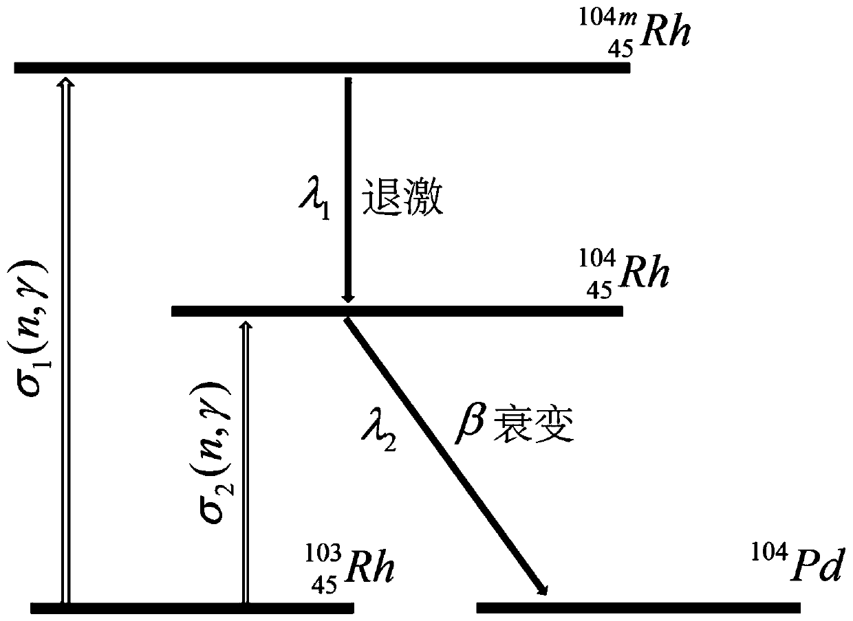
[0007] At present, many scholars at home and abroad have done a lot of research on rhodium self-sufficient energy detectors, and have obtained a lot of results, but also have some shortcomings: 1) the relevant literature often only contains the first and third parts, ignoring the second part, Although this part is not the main component of Rh, its role cannot be ignored considering the effect of correcting delay
2)
Method used
View moreImage
Smart ImageViewing Examples

Examples
 PUM
 Abstract
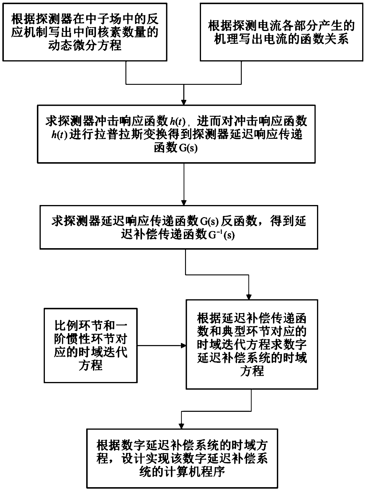
A method for eliminating a delay effect of a self-powered neutron detector based on a digital circuit comprises the following design steps: according to a physical process of a detector emitter material in a neutron field, writing a relational expression between current I(t) and the number of nuclides and neutron flux density phi(t); solving the impact response of the detector, and carrying out Laplace transformation on the impact response function of the detector to obtain a delay response transfer function G(s) = I(s)/phi(s) of the detector; solving an inverse function to obtain a delay correction transfer function G<-1>(s) = 1/G(s); and designing a digital delay compensation program according to the time domain iterative equation corresponding to each link in the transfer function G<-1>(s) = I(s)/phi(s). The method can correct the delay current signal of the self-powered neutron detector, and overcomes the signal delay caused by the half-life period of intermediate nuclide. Comparedwith a method for correcting signal delay by an analog circuit, the system also has the advantages of flexible parameter adjustment and low possibility of being interfered by external link factors.
Description
technical field [0001] The invention belongs to the technical field of neutron detection, and in particular relates to a method for eliminating the delay effect of a self-powered neutron detector based on a digital circuit. Background technique [0002] Nuclear energy is the most promising future energy source for mankind. In a nuclear reactor, the neutron flux density is the physical quantity that can most intuitively reflect the power of the reactor and the status of the reactor. At the same time, people also control the reactor by controlling the neutron flux density in the reactor. Due to the particularity of nuclear reactors and the importance of safe operation of nuclear reactors, neutron detection plays a vital role in the detection of various particles and rays in the reactor. [0003] The internal detection environment of the reactor core is complex, and its requirements for neutron detectors are relatively high, such as high temperature resistance, radiation resis...
Claims
Login to View More Application Information
Patent Timeline
 IPC IPC(8): G06F17/14G06F17/15G01T3/00
CPCG01T3/00G06F17/14G06F17/15
Inventor张清民吴孟祺安旅行邵壮
OwnerXI AN JIAOTONG UNIV