Built-in permanent magnet motor

A permanent magnet motor, built-in technology, applied in magnetic circuits, electrical components, electromechanical devices, etc., can solve the problem of unprovided power density, etc., achieve the improvement of the back EMF coefficient, improve the structural strength, and reduce the self-intersection of the rotor slot bottom. The effect of magnetic flux leakage

Pending Publication Date: 2019-12-10
GUANGDONG WELLING ELECTRIC MACHINE MFG
View PDF0 Cites 0 Cited by
  • Summary
  • Abstract
  • Description
  • Claims
  • Application Information

AI Technical Summary

Problems solved by technology

However, the above-mentioned patents only rely on parameters such as stator slot width, tooth width, and yoke width to average the flux density, and fail to consider the influence of the stator shape and structure on the motor magnetic field and loss, etc., and are not suitable for high power density motor structures. , also in order to reduce the vibration and noise of the motor through the combination method between the stator core and the casing, no structure that can comprehensively consider the power density and suppress vibration and noise

Method used


Image

  • Built-in permanent magnet motor
  • Built-in permanent magnet motor
  • Built-in permanent magnet motor

Examples


Embodiment Construction

[0058] Specific embodiments of the present invention will be described in detail below in conjunction with the accompanying drawings. It should be understood that the specific embodiments described here are only used to illustrate and explain the present invention, and are not intended to limit the present invention.

[0059] It should be noted in advance that in the description of the present application, "axial" generally refers to the axial direction of the motor, that is, the extending direction along the rotation axis of the motor.

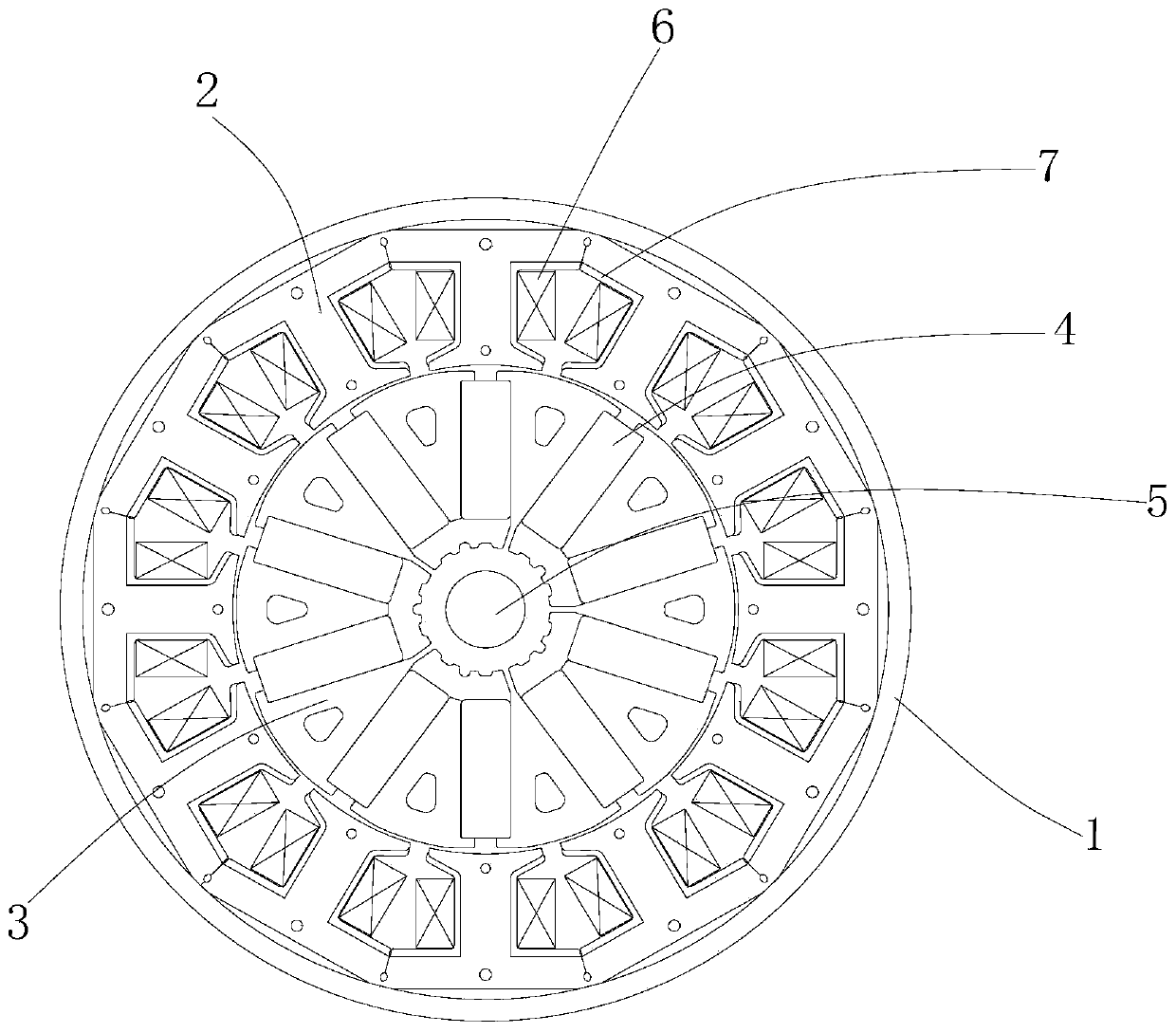
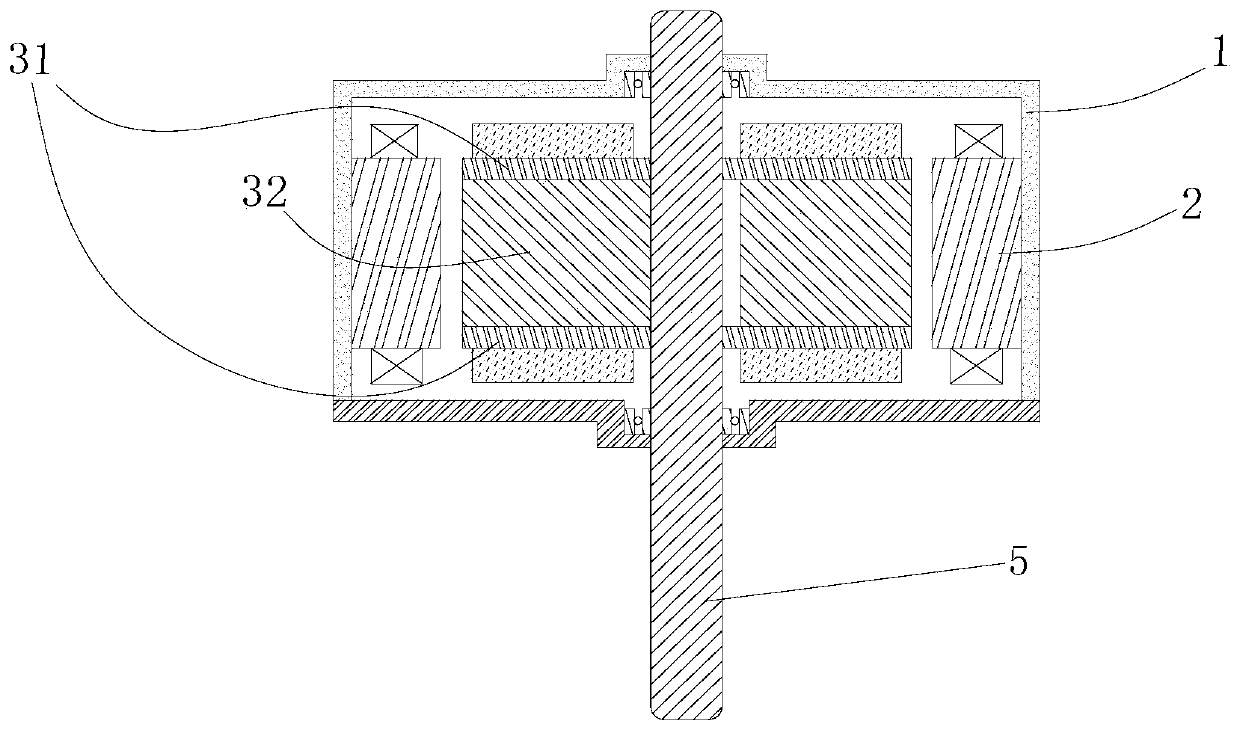
[0060] Such as figure 1 , Figure 5 and Figure 6 As shown, an embodiment of the present invention is a permanent magnet brushless DC motor, including a casing 1 , a stator core 2 , a rotor core 3 , a permanent magnet 4 , a shaft 5 , a winding 6 and an insulating frame 7 . The stator core 2 is arranged circumferentially along the inner wall of the casing 1, and the rotor core 3 is installed in the space surrounded by the stator core 2; the...


PUM


Abstract

The invention relates to the field of a permanent magnet motor and discloses a built-in permanent magnet motor. The motor comprises a casing, a stator core, a rotor core and a permanent magnet, wherein the rotor core comprises at least two full-connection bridge type lamination groups and at least one semi-connection bridge type lamination group, laminations in the full-connection bridge type lamination groups comprise a plurality of full-connection bridge laminations which are connected with a first central connection bridge and are distributed along the circumferential direction, laminationsin the semi-connection bridge type lamination group comprise at least one separation punching sheet which is disconnected with the second central connection bridge and is distributed along the circumferential direction, and the full-connection bridge type lamination groups and the semi-connection bridge type lamination group are stacked in the axial direction, so each semi-connection bridge typelamination group is located between the two full-connection bridge type lamination groups, adjacent sectors in the same lamination layer of the full-connection bridge type lamination groups are asymmetric, and the permanent magnets are placed in grooves between the adjacent sectors. The motor is advantaged in that the production process of the motor can be simplified, and the structural strength of the motor can be improved.

Description

technical field [0001] The invention relates to the field of permanent magnet motors, in particular to a built-in permanent magnet motor. Background technique [0002] Traditional brushless DC motors use surface-mounted magnetic tiles or built-in radially magnetized magnet steel structures, which have low power density and are limited by cost factors. The magnetic flux per pole of the motor is increased by tangentially magnetized parallel magnetic circuit structures. The existing tangential magnetization structure still has the problem of large flux leakage, which limits the performance improvement of the motor. [0003] In the existing rotor iron core, at least one tooth sector is disconnected from the rotor collar, and at least one tooth sector is connected to the shaft sleeve. This suppresses magnetic flux leakage near the axis. The rotor iron core shaft sleeve is provided with a positioning protrusion for positioning and supporting the permanent magnet. According to t...

Claims


Application Information

Patent Timeline
Patent Type & Authority Applications(China)
IPC IPC(8): H02K1/28H02K1/27
CPCH02K1/2706H02K1/28H02K2201/06H02K2213/03
Inventor 李文瑞甘峰李虎迟闯于明湖
Owner GUANGDONG WELLING ELECTRIC MACHINE MFG
Why Eureka
Try Eureka