Lens position adjusting method and device

A technology for adjusting devices and adjusting methods, which is applied in the field of electronics and can solve problems such as cumbersome steps and slow speed

Active Publication Date: 2019-12-10
BEIJING XIAOMI MOBILE SOFTWARE CO LTD
View PDF2 Cites 5 Cited by
  • Summary
  • Abstract
  • Description
  • Claims
  • Application Information

AI Technical Summary

Problems solved by technology

[0005] The present disclosure provides a lens position adjustment method and device, whi

Method used


Image

  • Lens position adjusting method and device
  • Lens position adjusting method and device
  • Lens position adjusting method and device

Examples


Embodiment Construction

[0074] In order to make the purpose, technical solutions and advantages of the present disclosure clearer, the present disclosure will be further described in detail below in conjunction with the accompanying drawings. Apparently, the described embodiments are only some of the embodiments of the present disclosure, not all of them. Based on the embodiments in the present disclosure, all other embodiments obtained by persons of ordinary skill in the art without creative efforts fall within the protection scope of the present disclosure.

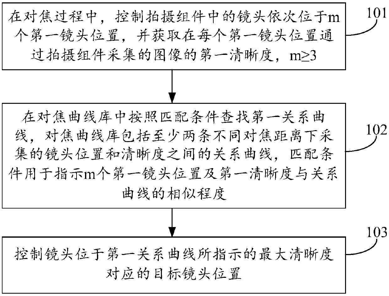
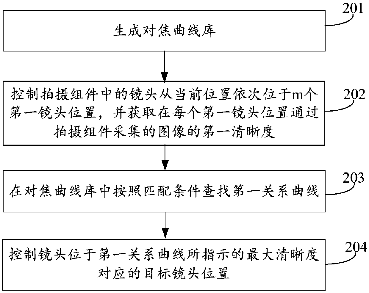
[0075] With the development of electronic technology, when a camera or a terminal (such as a mobile phone) captures an image, the lens in the shooting component can be automatically moved to the target lens position, so that a clear image can be collected through the shooting component. However, when determining the target lens position, the number of times to control the lens to move is relatively large, resulting in cumbersome and slow steps ...


PUM


Abstract

The invention relates to a lens position adjusting method and device, and belongs to the technical field of electronics. The method comprises the steps that in the focusing process, lenses in a shooting assembly are controlled to be sequentially located at m first lens positions, the first definition of an image collected through the shooting assembly at each first lens position is obtained, and mis larger than or equal to 3; a first relation curve in a focusing curve library is searched according to a matching condition, the focusing curve library comprises at least two relation curves between lens positions and sharpness acquired at different focusing distances, and the matching condition is used for indicating m first lens positions and similarity degrees between the first sharpness and the relation curves; and the lens is controlled to be located at a target lens position corresponding to the maximum definition indicated by the first relation curve. According to the invention, theproblems of tedious steps and slow speed of lens position adjustment are solved, the steps of lens position adjustment are simplified, and the speed of lens position adjustment is improved. The invention is used for adjusting the lens position.

Description

technical field [0001] The present disclosure relates to the field of electronic technology, in particular to a method and device for adjusting a lens position. Background technique [0002] With the development of electronic technology, most terminals (such as mobile phones) have a camera function, and the terminal can automatically adjust the position of its lens, so that the terminal can collect clear images through the lens. [0003] In the related art, when the terminal adjusts the position of its lens, it needs to control the lens to move multiple times, so as to determine the range of the lens position in which a clearer image can be collected. Next, the terminal needs to control the lens to move several times within the range of the lens position, and determine the position of the lens within the range of the lens position where the clearest image can be collected. Afterwards, the terminal can control the lens to be at the lens position. [0004] In the related art...

Claims


Application Information

Patent Timeline
IPC IPC(8): H04N5/232
CPCH04N23/67G03B13/36H04N23/673H04N23/90G02B7/28
Inventor 乔张陈小龙王昆鹏
Owner BEIJING XIAOMI MOBILE SOFTWARE CO LTD
Why Eureka
Try Eureka