Method of manufacturing optical head

a manufacturing method and head technology, applied in the direction of instruments, disposition/mounting of heads, light beam reproducing, etc., can solve the problems of difficult reduction in size and thickness of optical heads, difficult to individually adjust their positions, etc., to achieve easy relative position adjustment, simplify configuration, and reduce the effect of size and thickness of apparatus

a manufacturing method and head technology, applied in the direction of instruments, disposition/mounting of heads, light beam reproducing, etc., can solve the problems of difficult reduction in size and thickness of optical heads, difficult to individually adjust their positions, etc., to achieve easy relative position adjustment, simplify configuration, and reduce the effect of size and thickness of apparatus

US7209411B1Inactive Publication Date: 2007-04-24PANASONIC CORP

Image

  • Method of manufacturing optical head
  • Method of manufacturing optical head
  • Method of manufacturing optical head

Examples


first embodiment

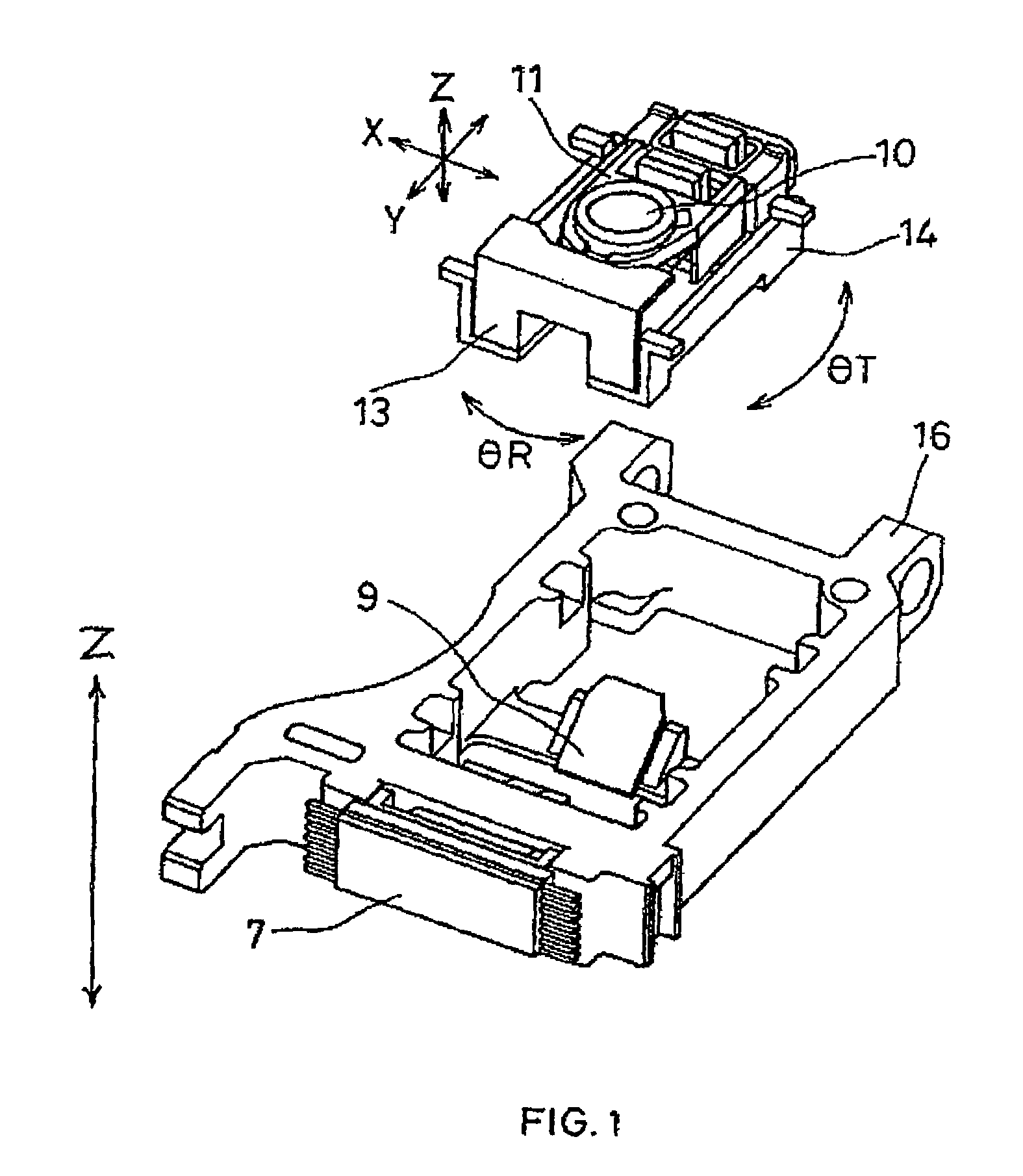
[0046]A first embodiment of the present invention is described with reference to the drawings as follows.

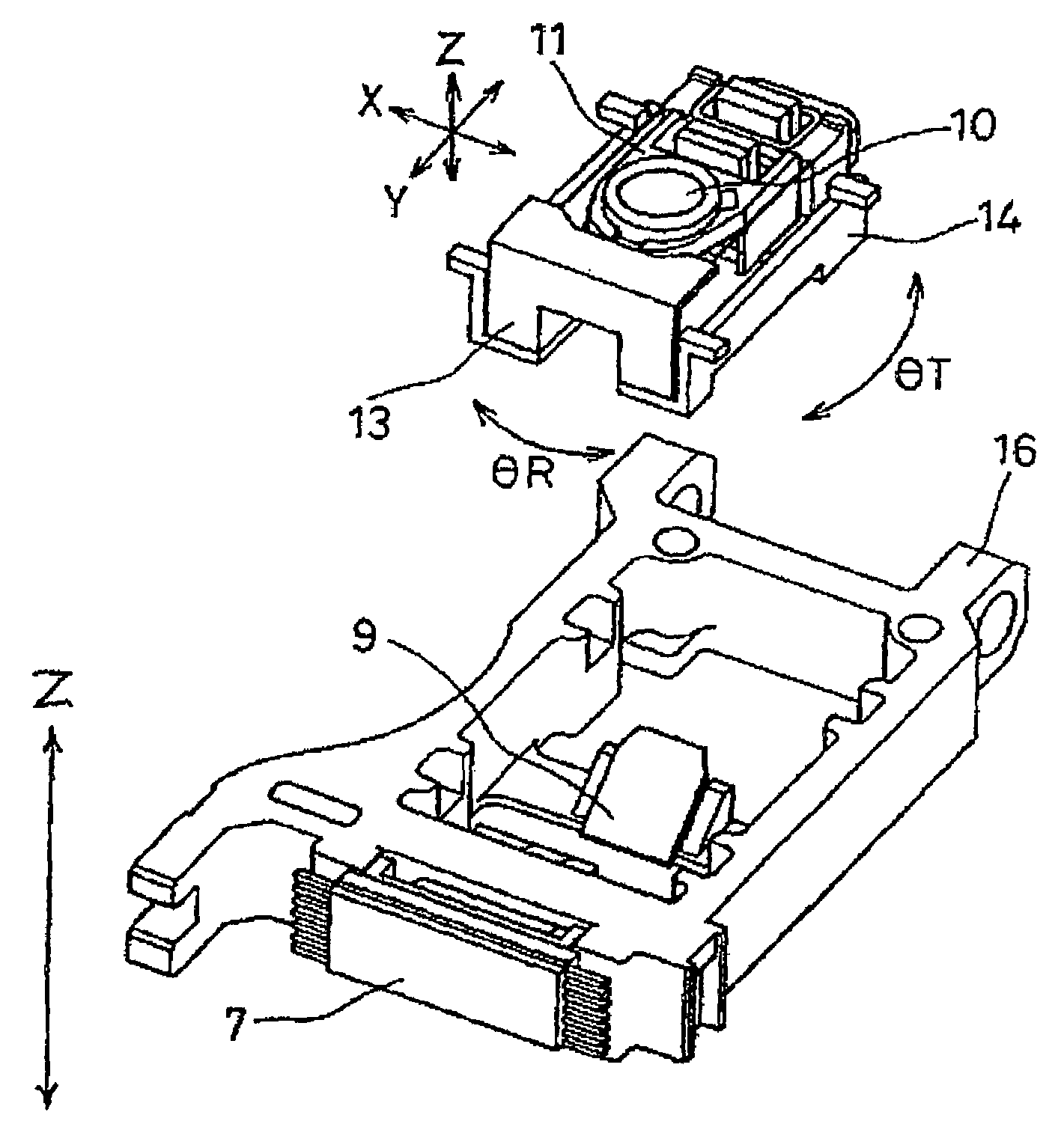
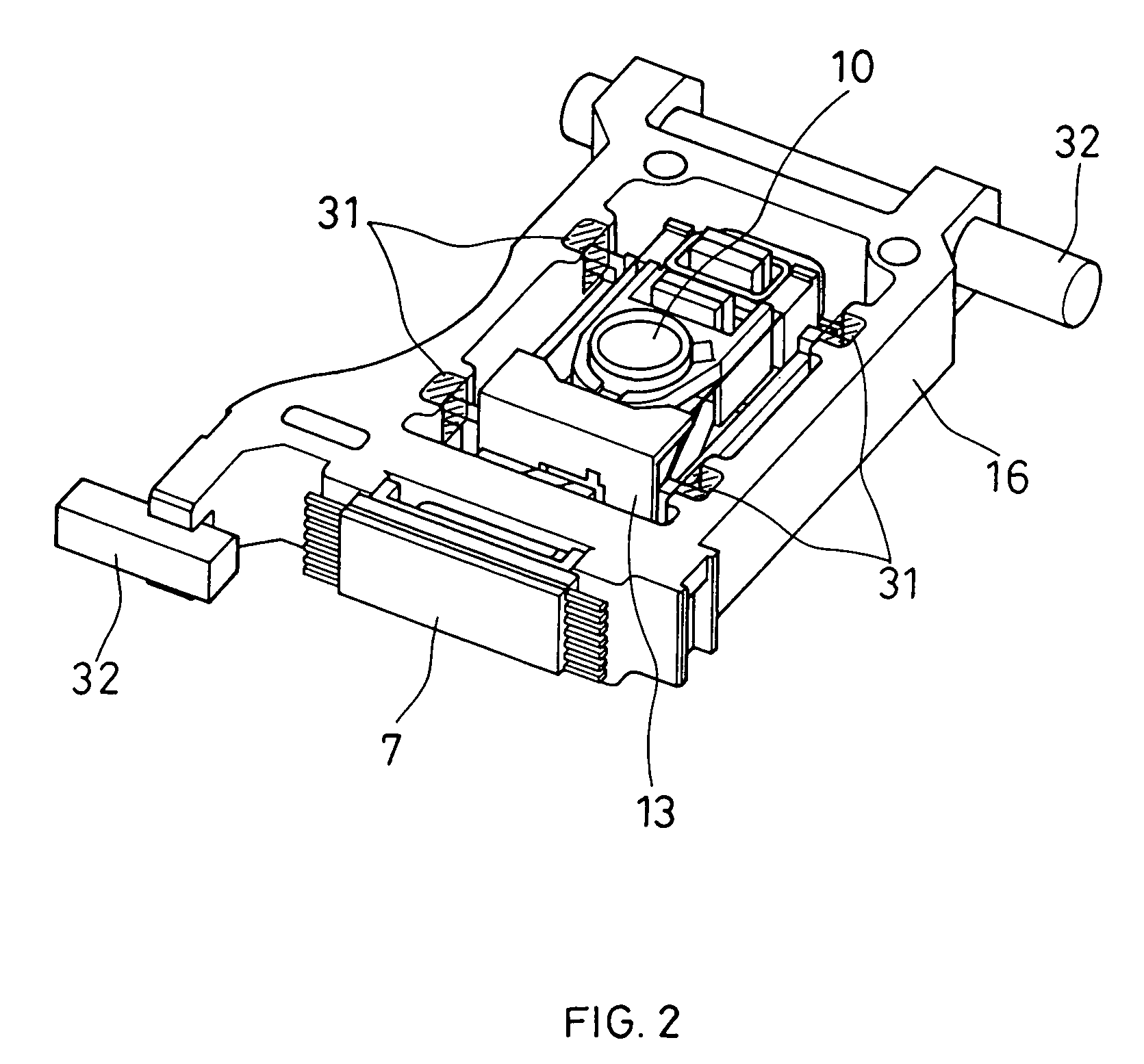
[0047]In FIGS. 1, 2, 3, 4, and 5, numeral 1 indicates a silicon substrate, numeral 2 a semiconductor laser fixed on the silicon substrate 1, numeral 3 a multisplit photodetector provided on the silicon substrate 1, numeral 4 a resin package, and numeral 5 a hologram element (a diffraction grating) formed of resin. The semiconductor laser 2, the multisplit photodetector 3, and the hologram element 5 are fixed to the resin package 4 with high precision. Numeral 6 denotes a composite device including a beam splitter 6a, a return mirror 6b, and a polarization separation element 6c. Numeral 9 represents a reflecting mirror, numeral 10 an objective lens fixed to an objective lens holder 11, numeral 12 a magneto-optical recording medium having a magneto-optical effect, numeral 13 an objective lens actuator for actuating the objective lens in a focus direction and a radial direction of t...

second embodiment

[0063]Next, a second embodiment is described with reference to FIG. 6.

[0064]The present embodiment is different from the first embodiment in that the adjustment of a base 14 in a Y direction (a tangential direction) is achieved by the adjustment of a reflecting mirror 9 in a Z′ direction.

[0065]According to this configuration, the volume of adjustment of an objective lens actuator 13 and the base 14 in the Y direction (the tangential direction) can be reduced considerably, thus further reducing the size of the optical head.

third embodiment

[0066]Next, a third embodiment is described with reference to FIG. 7.

[0067]The present embodiment is different from the first embodiment in that a base 14 also is adjusted in a Z direction (in a direction of an axis of incident light, the height direction). According to this configuration, offset of a focus error signal can be eliminated, thus enabling recording and reproduction with high precision and low electricity.


PUM

PropertyMeasurementUnit
diameteraaaaaaaaaa
optical axisaaaaaaaaaa
relative angleaaaaaaaaaa

Abstract

An integrated unit in which a light source and a light emitting diode are combined into one component is fixed to an optical bench. Then, relative position adjustment of an objective lens actuator is carried out with respect to the optical bench so that a desired detection signal can be obtained through reflected light from a disk information recording medium and then the objective lens actuator is fixed. The relative position adjustment of the integrated unit is no longer required and it is no longer necessary preliminarily to provide a margin for adjusting the integrated unit. Thus, an optical head can be reduced in size and thickness.

Description

FIELD OF THE INVENTION[0001]The present invention relates to a method of manufacturing an optical head for a disk recording / reproducing apparatus using a system of optically recording or reproducing information by projecting a light spot on a disk recording medium.BACKGROUND OF THE INVENTION[0002]Recently, disk recording / reproducing apparatuses have been used for many applications, such as for DVDs, MDs, CDs, CD-ROMs, or the like, which have been diversified year after year. In addition, they have been increasingly improved in density, performance, quality and added value, and reduced in size. Particularly, in disk recording / reproducing apparatuses using recordable magneto-optical media, the demand for those used for data and picture recording tends to increase considerably, and further reductions in size and thickness and further improvement in performance and recording density have been requested.[0003]Conventionally, many techniques relating to optical heads for magneto-optical d...

Claims


Application Information

Patent Timeline
24 Apr 2007
Publication
US7209411B1
IPC
G11B7/00; G11B7/08; G11B7/085; G11B7/12; G11B7/123; G11B7/135; G11B7/1362; G11B7/1372; G11B7/22; G11B11/105
CPC
G11B7/082; G11B7/123; G11B7/1362; G11B7/1372; G11B7/22; G11B7/08582; G11B11/1055
Inventors
NAKATA, HIDEKI; TOMITA, HIRONORI