
Novel concept pot

A new concept, pot lid technology, applied in multi-unit cooking utensils, overflow prevention, cooking utensil lids, etc., can solve problems such as defective overflow prevention function, inability to use steamer, and failure to solve the problem of lid opening and closing. Ideal overflow effect, strong practical effect

Inactive Publication Date: 2019-12-13
洪文明
View PDF6 Cites 1 Cited by
  • Summary
  • Abstract
  • Description
  • Claims
  • Application Information

AI Technical Summary

Problems solved by technology

troublesome, wasteful, unhygienic;
[0005] 2. The amount of water added is limited by the scale line—it cannot exceed the maximum scale line, otherwise it will cause overflow, short circuit, and unsafe;
[0006] 3. Do not use the steamer to steam or heat the food while cooking the food, because the juice will flow into the steamer and contaminate the food;
The practicality of the steamer is too poor, it is basically a redundant part;
[0008] 5. Because the anti-overflow function is defective, the heating time of cooking food has to be set to: the whole process from the beginning of heating to the end of heating
waste of time, waste of energy;
[0009] 6. It takes 3 hours for three meals a day on average, which is a waste of time;
[0010] 7. An average of three meals a day requires 3 kilowatt-hours of electricity, wasting energy;
[0015] 1. It is wrong to set the lid button on the front of the operation panel of the pot table, and it cannot be manufactured.
Because the upper buckle of the pot lid button is a step set on the edge of the inner reinforcement ring of the pot lid, and this step causes the pot lid to be unable to be demolded after injection molding; The front of the pot body is also impossible to manufacture, because the electric plate bracket is in the way next to the inner wall in front of the pot body, and it cannot be connected to the pot cover in any form.
[0016] In short, the described lid switch problem is not solved;
[0017] 2. There are too many spokes at the bottom of the groove of the pot cover, which affects the smooth flow of steam and wastes materials;
[0018] 3. The steamer has the following defects: 1. The height of the steamer is 75mm, minus the 7mm height of the anti-blocking ring at the bottom of the cage, and subtracting the 3.5mm thickness of the bottom of the cage, there is only 64.5mm, but the height of the bowl 70mm, it is impossible to steam food with a bowl; 2. The four air outlets evenly distributed in the anti-blocking ring are too few, and the steam circulation is not smooth; 3. The height of the cross-section of the anti-blocking ring and the anti-blocking column is 7mm, which is too small One point, the steam flow is not smooth;
[0019] 4. The design of the steamer cover is superfluous, which not only wastes materials, but also troublesome operation;
[0020] 5. The length of the air duct accounts for more than 90% of the circumference. If it is too long, it is unnecessary, increases the complexity of the process, and wastes materials;
[0021] 6. The design of the mounting plate on the fan outlet is wrong, and the two holes at one end are blocked by the fuselage during installation, so it cannot be installed;
[0022] 7. The base of the pot body has three defects: 1. The height of the four slopes at the front, rear, left, and right is too low, which is not beautiful; Function; three or four legs are too large, bulky and ugly, and waste materials;
[0023] 8. No power outlets

Method used


Image

  • Novel concept pot
  • Novel concept pot
  • Novel concept pot

Examples


Embodiment Construction

[0086] The present invention will be further described below in conjunction with the accompanying drawings and specific implementation methods.

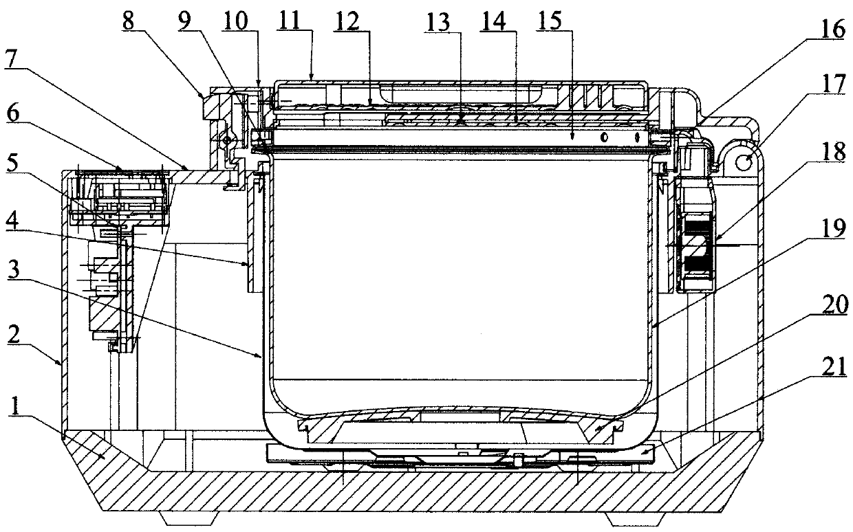
[0087] figure 1 It is a sectional view of the new concept pot.

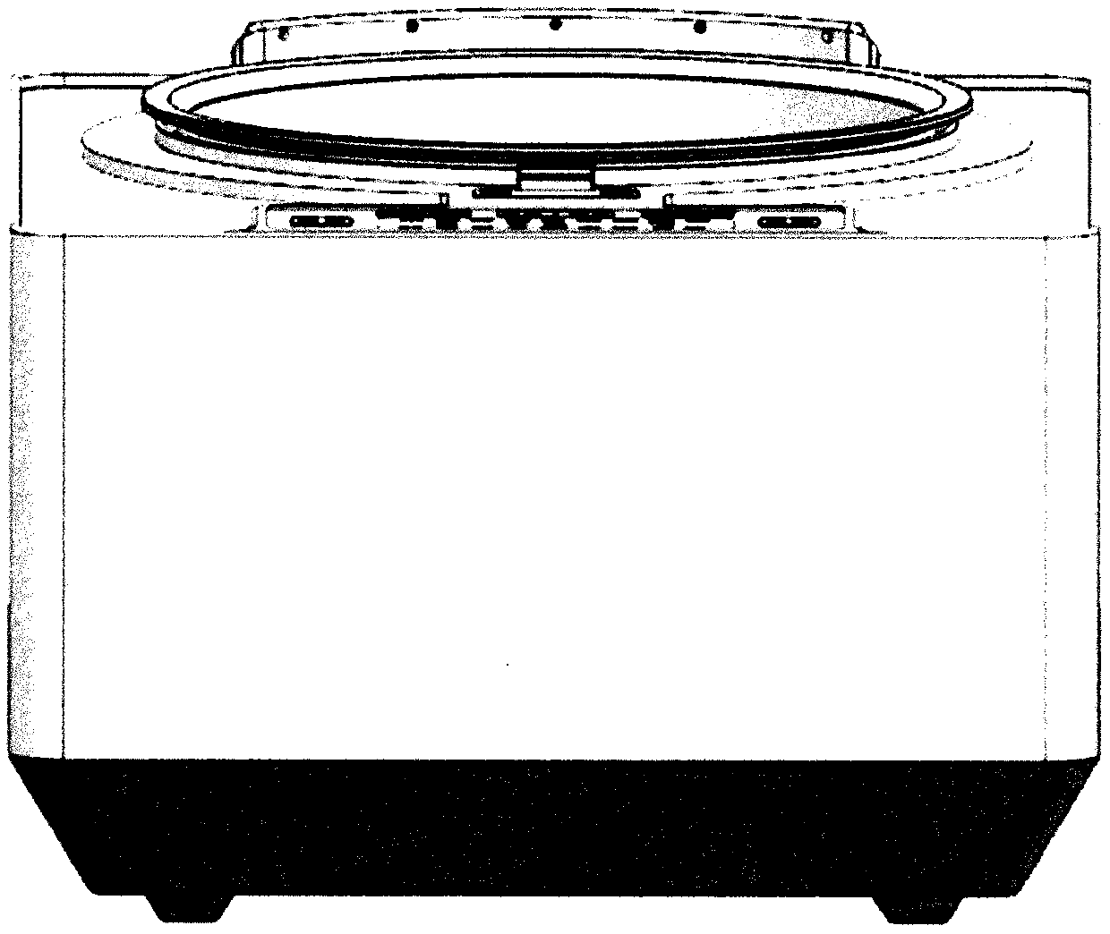
[0088] figure 2 It is the cuboid casing of the new concept pot body, the upper end surface of the cuboid casing is a pot platform, an operation panel is set in the center of the front of the pan platform, and a pot cover switch is set at the rear of the operation panel to buckle;

[0089] A circular hollow window is set behind the button of the lid switch; an outer pot is set in the circular hollow window; an inner pot is set on the mouth of the outer pot; the outer pot and the inner pot are clearance fit; Air ducts are set on the edge of the rear end of the pot;

[0090] Below the pot platform, a blower fan is set in the cavity between the outer pot and the casing of the pot body; the air duct air inlet and the fan air outlet on the pot platform are seamlessly conn...


PUM

PropertyMeasurementUnit
Depthaaaaaaaaaa
Heightaaaaaaaaaa
Heightaaaaaaaaaa

Abstract

The invention discloses a novel concept pot. The novel concept pot comprises a single-body pot and a double-body pot, wherein the single-body pot comprises a pot body, a pot platform, a pot cover, a chip, a pot cover switch, a round hollow window, an outer pot, an inner pot, an air duct, a draught fan, a pot body base, an auxiliary cover and a food steamer. The pot body is a rectangular box body;the pot platform is arranged above the box body, an operation panel and the pot cover are sequentially arranged on the pot platform from the front edge to the rear edge, the chip is arranged at a center point above a metal cover plate of the pot cover, the pot cover switch is arranged at the front end of the pot cover, the circular hollow window is arranged below the pot cover, the inner pot and the outer pot are arranged in the circular hollow window, and the air duct is arranged at the rear edge of the inner pot; the auxiliary cover and the food steamer are arranged in the circular groove ofthe pot cover; the draught fan is arranged in the cavity between the outer pot and the pot body; the pan body base is arranged at the bottom of the box body, a tray is arranged in the pan body base,the outer pan is supported by the tray, a heating plate is arranged on the bottom surface of the outer pan, and the inner pan is supported by the heating plate. Two single-body pots are mounted in onepot body to form a double-body pot. Compared with a microcomputer electric rice cooker, the novel concept pot has ten absolute advantages of ideal anti-overflow effect, time saving and energy savingeffects up to more than 60% and the like.

Description

technical field [0001] The invention belongs to the field of kitchen appliances, and in particular relates to a new concept pot. Background technique [0002] 1. Microcomputer electric rice cooker; 2. An improved anti-overflow cooker, application number: 201710032323.2. [0003] The above background technology "1" has the following 10 congenital defects: [0004] 1. When cooking food, there is always juice foam sticking to the pot cover or even gushing out of the pot cover. The pot cover must be removed and washed frequently. troublesome, wasteful, unhygienic; [0005] 2. The amount of water added is limited by the scale line—it cannot exceed the maximum scale line, otherwise it will cause overflow, short circuit, and unsafe; [0006] 3. Do not use the steamer to steam or heat the food while cooking the food, because the juice will flow into the steamer and contaminate the food; [0007] 4. The steamer is built into the mouth of the inner pot. The height of the steamer i...

Claims


Application Information

Patent Timeline
IPC IPC(8): A47J27/00A47J36/06A47J27/04A47J27/12A47J27/56
CPCA47J27/004A47J27/04A47J27/12A47J27/56A47J36/06A47J2027/043
Inventor 洪文明
Owner 洪文明
Learn More