A portable wooden board side chamfering equipment

A portable, wood-based technology, used in metal processing equipment, grinding/polishing equipment, grinding skateboards, etc., it can solve the problems of uneven movement of the plane, low chamfering efficiency, and irregular chamfering, saving manpower, reducing downtime. High corner efficiency and smooth chamfering effect

Active Publication Date: 2021-05-07
江西启来标识有限公司
View PDF8 Cites 0 Cited by
  • Summary
  • Abstract
  • Description
  • Claims
  • Application Information

AI Technical Summary

Problems solved by technology

When processing wood boards, people often chamfer the side of the board to remove the burrs on the side of the board. At present, people generally use a plane to chamfer the side of the board. People hold the plane and push it back and forth on the board. In this way, the burrs on the side of the board are removed to form chamfers. After a long time of operation, people's hands are prone to soreness, which requires more manpower, and the chamfering efficiency is low. When pushing the plane to move, it is not stable, resulting in uneven chamfering , asymmetrical

Method used


Image

  • A portable wooden board side chamfering equipment
  • A portable wooden board side chamfering equipment
  • A portable wooden board side chamfering equipment

Examples


Embodiment 1

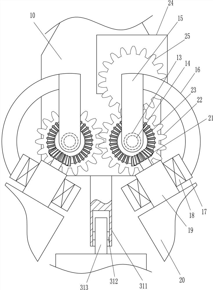
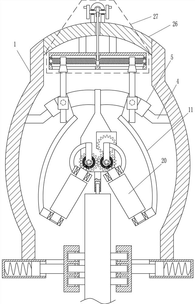
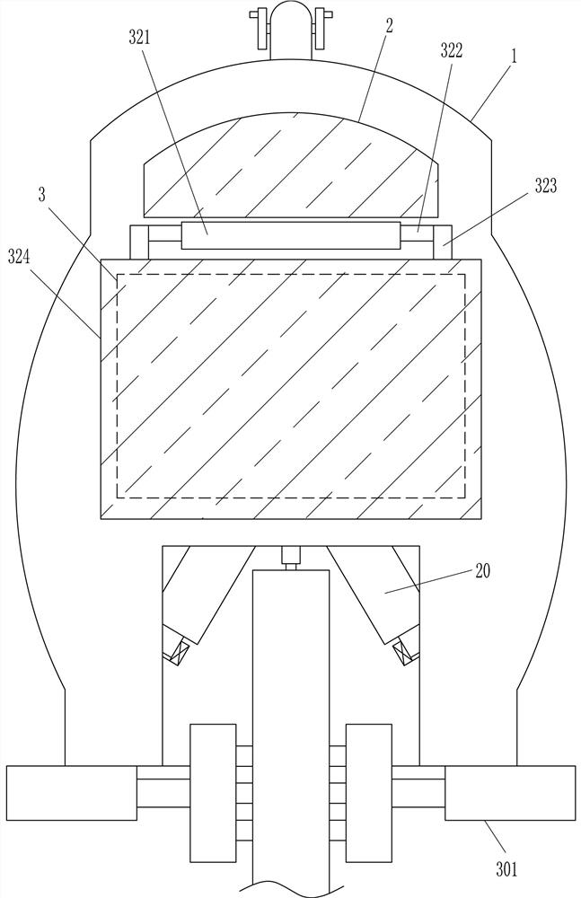
[0019] A portable device for chamfering the sides of wooden boards, such as Figure 1-5 As shown, it includes an installation box 1, an observation window 2, a connecting frame 4, an arc slide rail 5, a first slider 6, a first rotating shaft 7, a first guide sleeve 8, a first guide rail 9, a mounting plate 10, a curved Rod 11, first connecting block 12, first bearing housing 13, first rotating rod 14, first rotating block 15, connecting arm 16, second connecting block 17, second bearing housing 18, second rotating rod 19, grinding wheel 20. The first bevel gear 21, the first gear 22, the second bevel gear 23, the driving motor 24, the second gear 25, the top cover 26 and the moving device 27, and the upper front side of the installation box 1 is provided with an observation window 2 The middle part of the front side of the installation box 1 has an operation hole 3, and the upper parts of the left and right sides of the installation box 1 are connected with the connecting fram...

Embodiment 2

[0021] A portable device for chamfering the sides of wooden boards, such as Figure 1-5As shown, it includes an installation box 1, an observation window 2, a connecting frame 4, an arc slide rail 5, a first slider 6, a first rotating shaft 7, a first guide sleeve 8, a first guide rail 9, a mounting plate 10, a curved Rod 11, first connecting block 12, first bearing housing 13, first rotating rod 14, first rotating block 15, connecting arm 16, second connecting block 17, second bearing housing 18, second rotating rod 19, grinding wheel 20. The first bevel gear 21, the first gear 22, the second bevel gear 23, the driving motor 24, the second gear 25, the top cover 26 and the moving device 27, and the upper front side of the installation box 1 is provided with an observation window 2 , the middle part of the front side of the installation box 1 has an operation hole 3, and the upper parts of the left and right sides of the installation box 1 are connected with the connecting fra...

Embodiment 3

[0024] A portable plank side chamfering device such as Figure 1-6 As shown, it includes an installation box 1, an observation window 2, a connecting frame 4, an arc slide rail 5, a first slider 6, a first rotating shaft 7, a first guide sleeve 8, a first guide rail 9, a mounting plate 10, a curved Rod 11, first connecting block 12, first bearing housing 13, first rotating rod 14, first rotating block 15, connecting arm 16, second connecting block 17, second bearing housing 18, second rotating rod 19, grinding wheel 20. The first bevel gear 21, the first gear 22, the second bevel gear 23, the driving motor 24, the second gear 25, the top cover 26 and the moving device 27, and the upper front side of the installation box 1 is provided with an observation window 2 , the middle part of the front side of the installation box 1 has an operation hole 3, and the upper parts of the left and right sides of the installation box 1 are connected with the connecting frame 4, and the inner ...


PUM


Abstract

The invention relates to a chamfering device, in particular to a portable side chamfering device of a wooden board. The technical problem to be solved is to provide a portable plank side chamfering device that can save manpower, move smoothly, and chamfer neatly and symmetrically. The technical solution is: a portable side chamfering device for wooden boards, including a mounting box, an observation window, a connecting frame, an arc slide rail, a first slider, a first rotating shaft, a first guide sleeve, etc.; the front side of the mounting box There is an observation window on the upper part, and an operation hole is opened in the middle part of the front side of the installation box. The present invention drives the left and right first guide rails to move inward or outward through the moving device, thereby driving the first connecting blocks on the left and right to move outward or inward, thereby making the lower parts of the grinding wheels on the left and right outward or inward Swing, so that the chamfering angle of the side of the board can be adjusted; the grinding wheel is driven by the drive motor to chamfer the side of the board, and the chamfering can be done without pushing the plane by hand, which can save manpower and has high chamfering efficiency.

Description

technical field [0001] The invention relates to a chamfering device, in particular to a portable side chamfering device of a wooden board. Background technique [0002] Chamfering refers to the processing of cutting the corners of the workpiece into a certain slope. When processing wood boards, people often chamfer the side of the board to remove the burrs on the side of the board. At present, people generally use a plane to chamfer the side of the board. People hold the plane and push it back and forth on the board. In this way, the burrs on the side of the board are removed to form chamfers. After a long time of operation, people's hands are prone to soreness, which requires more manpower, and the chamfering efficiency is low. , Asymmetry. Contents of the invention [0003] In order to overcome the hand-held planer chamfering the side of the wooden board is easy to be sore, it needs more manpower, and the chamfering efficiency is low, the chamfering is not neat and asy...

Claims


Application Information

Patent Timeline
Patent Type & Authority Patents(China)
IPC IPC(8): B24B9/18B24B41/02B24B47/12
CPCB24B9/18B24B41/02B24B47/12
Inventor 陈明星
Owner 江西启来标识有限公司
Why Eureka
Try Eureka