Vacuum excavation head

A vacuum and material head technology, which is applied in earth movers/shovels, mechanically driven excavators/dredgers, construction, etc., can solve the problems of inconvenient, inconvenient, and labor-intensive operation of high-pressure water guns and excavation heads. Achieve the effects of avoiding high-pressure water jets from hurting people, easy to use, and improving work efficiency

Pending Publication Date: 2019-12-13
SHANDONG ROADWAY CONSTR MACHINERY MFG
View PDF0 Cites 0 Cited by
  • Summary
  • Abstract
  • Description
  • Claims
  • Application Information

AI Technical Summary

Problems solved by technology

However, in the excavation project, the operation of the high-pressure water gun and the excavation head is quite inconvenient. It often requires two operators to operate the high-pressure water gun and the excavation head respectively, which consumes manpower and requires two operators to cooperate with each other, which is quite inconvenient

Method used


Image

  • Vacuum excavation head
  • Vacuum excavation head
  • Vacuum excavation head

Examples


Embodiment 1

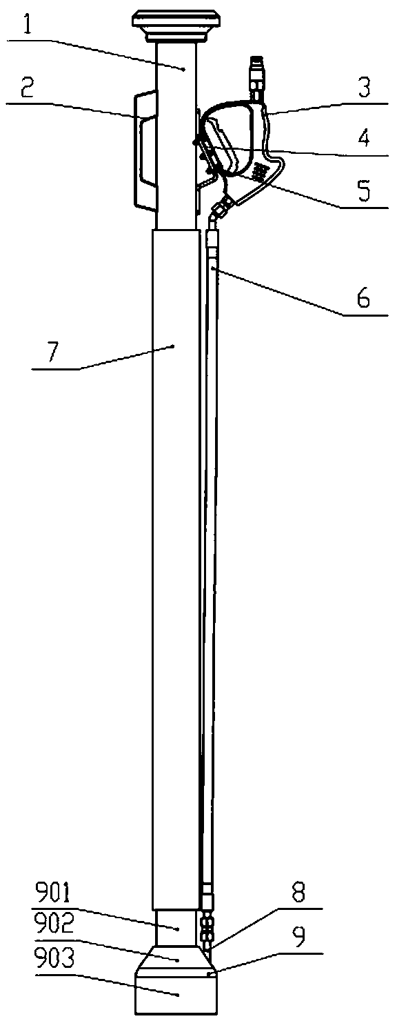
[0024] A vacuum excavation head, such as figure 1 and figure 2 As shown, it includes a connection joint 1, a high-pressure water gun 3, a water delivery hose 6, a suction pipe 7, a suction head 9, and a nozzle water supply channel. The connection joint 1 is welded to the upper end of the suction pipe 7 or connected by threads The suction head 9 is welded or fixed on the lower end of the suction pipe 7 through threaded connection, and also includes a pressure plate 4, the high-pressure water gun 3 is fixed on the connection joint 1 through the pressure plate 4, and the connection joint 1 is welded and fixed with a mounting seat , the pressure plate 4 is fixed on the mounting seat of the connecting joint 1 by connecting bolts 5 . The nozzle water supply passage communicates with the water delivery rubber hose 6 outside the suction head 9. A preset number of high-pressure nozzles 11 are installed on the nozzle water supply passage. The number of high-pressure nozzles 11 is 3-4....

Embodiment 2

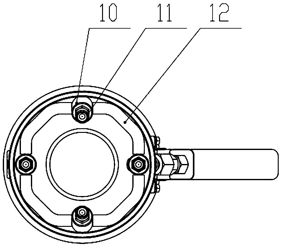
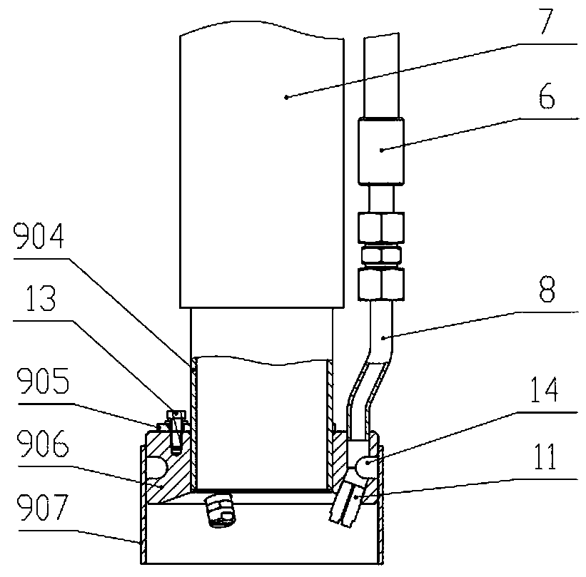
[0029] The difference between embodiment 2 and embodiment 1 is that the structure of suction head 9 is different, as image 3 As shown, the specific structure is as follows:

[0030]A vacuum excavation head, including a connection joint 1, a high-pressure water gun 3, a water delivery hose 6, a material suction pipe 7, a material suction head 9, and a nozzle water supply channel, and the connection joint 1 is welded to the upper end of the material suction pipe 7 or passed through Threaded connection, the suction head 9 is welded or fixed on the lower end of the suction pipe 7 by threaded connection, and also includes a pressure plate 4, the high-pressure water gun 3 is fixed on the connection joint 1 by the pressure plate 4, and the connection joint 1 is welded A mounting seat is fixed, and the pressing plate 4 is fixed on the mounting seat of the connecting joint 1 through connecting bolts 5 . The nozzle water supply passage communicates with the water delivery rubber hose ...


PUM


Abstract

The invention discloses a vacuum excavation head, and relates to the technical field of vacuum excavation. The vacuum excavation head comprises a connecting connector, a high-pressure water gun, a water conveying rubber pipe, a material suction pipe, a material suction head and a nozzle water supply passage, wherein the connecting connector is connected with the upper end of the material suction pipe, the material suction head is connected and fixed to the lower end of the material suction pipe, the high-pressure water gun is fixed on the connecting connector, the nozzle water supply passage communicates with the water conveying rubber pipe outside the material suction head, the nozzle water supply passage is provided with high-pressure nozzles in a preset number, the high-pressure nozzlesare arranged in the material suction head, and openings of the high-pressure nozzles face a material suction port of the material suction head. The vacuum excavation head can integrate the functionsof high-pressure water jet crushing and vacuum suction, single-person operation is achieved, labor cost is saved, and labor efficiency is improved.

Description

Technical field: [0001] The invention relates to the technical field of vacuum excavation, in particular to a vacuum excavation head. Background technique: [0002] Vacuum excavator is a brand new non-destructive excavation equipment. In the expansion, renovation and maintenance of municipal underground pipe network projects, it can achieve precise positioning and minimally invasive excavation on the ground; during the excavation process, the pipeline will not be damaged; it can also be hollowed out and excavated across the pipeline, Convenient pipeline maintenance. It sprays high-pressure water jets through high-pressure water guns, cuts, crushes and compacts the base layer to form granules or block materials; uses pneumatic conveying technology to suck particles or block materials from the vacuum excavation head for transportation. However, in the excavation project, the operation of the high-pressure water gun and the excavation head is quite inconvenient. Often, two op...

Claims


Application Information

Patent Timeline
IPC IPC(8): E02F3/88E02F3/90E02F3/92
CPCE02F3/88E02F3/8891E02F3/90E02F3/9262
Inventor 陈立文赵自立刘凯昃向博
Owner SHANDONG ROADWAY CONSTR MACHINERY MFG
Why Eureka
Try Eureka