Method for operating fuel injector and fuel injector

A technology of fuel injectors and functions, which is applied in the direction of fuel injection devices, special fuel injection devices, charging systems, etc., which can solve the problems of installation space and energy demand, and achieve the effect of large stroke

Inactive Publication Date: 2019-12-13
ROBERT BOSCH GMBH
View PDF5 Cites 0 Cited by
  • Summary
  • Abstract
  • Description
  • Claims
  • Application Information

AI Technical Summary

Problems solved by technology

However this can lead to installation space issues
In addition, the energy requirement increases

Method used


Image

  • Method for operating fuel injector and fuel injector
  • Method for operating fuel injector and fuel injector
  • Method for operating fuel injector and fuel injector

Examples


Embodiment Construction

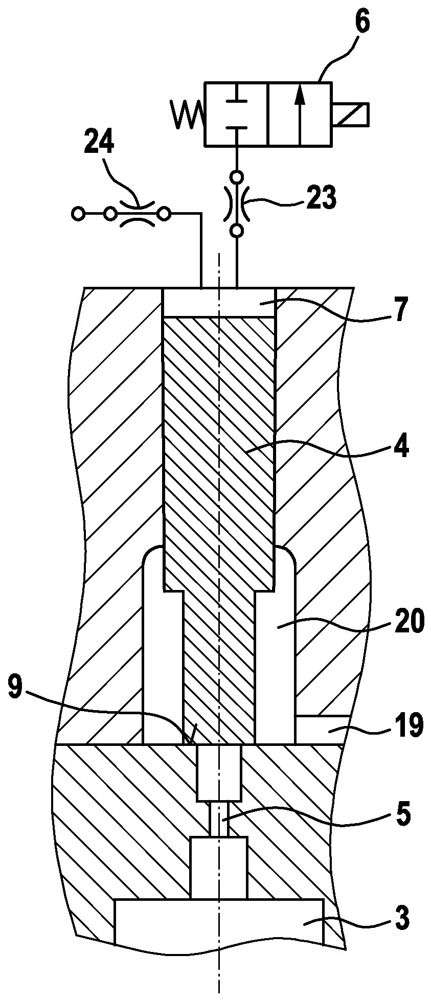
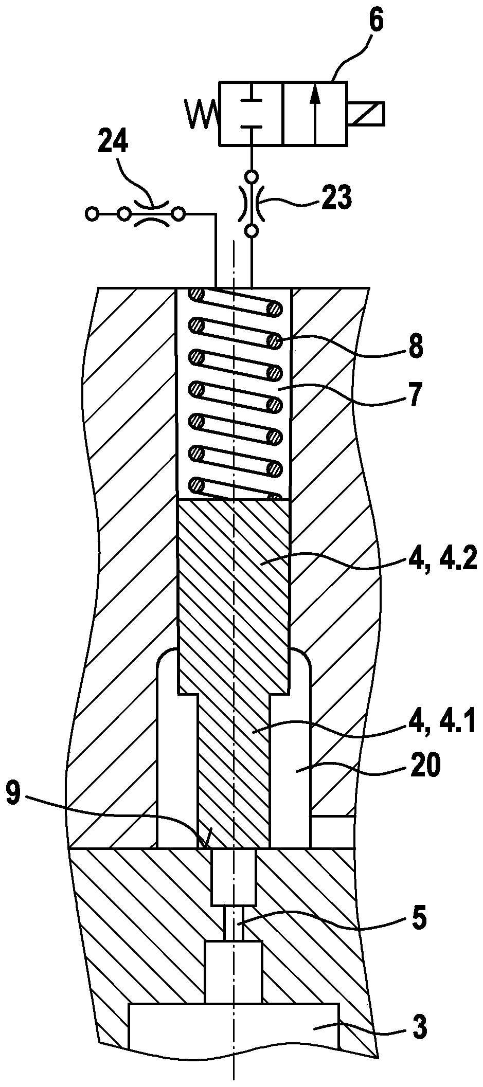
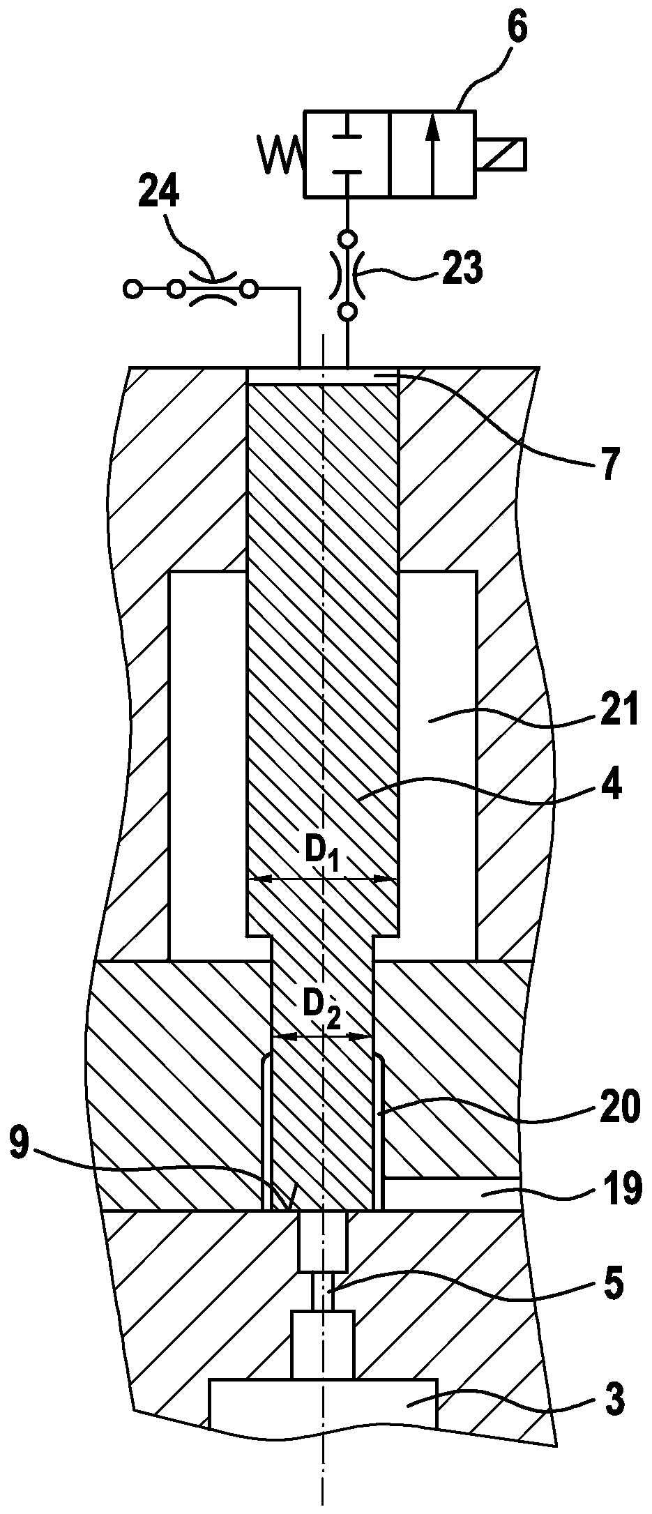
[0032] The fuel injector of the present invention may be similar to Figure 6 The embodiment of the fuel injector shown in , wherein a difference is made with regard to the hydraulic control of the outer nozzle needle 1 , which is designed as a hollow needle. The area is in Figure 6 marked by a dotted border. described in more detail below Figure 1 to Figure 5 All about the area.

[0033] From figure 1 A first preferred embodiment of the hydraulic control of the nozzle needle 1 is known. The hydraulic control takes place by means of a pilot control piston 4 , via the position of which the control pressure can be varied in a control chamber 3 , which is delimited by the nozzle needle 1 . This means that the control pressure present in the control chamber 3 acts on the nozzle needle 1 and exerts a hydraulic pressure on the nozzle needle 1 in the closing direction. Therefore, the control pressure in the control chamber 3 must be reduced in order to open the nozzle needle 1...


PUM


Abstract

The invention relates to a method for operating a fuel injector, in which the reciprocating motion of a nozzle needle (1) for releasing and closing at least one injection opening (2) is controlled hydraulically via a variable control pressure assigned to a control room (3) of the nozzle needle (1) and applied to the nozzle needle (1). According to the invention, the control pressure in the controlchamber (3) is changed with the aid of a likewise hydraulically controlled and reciprocable pilot control piston (4) which switches an outlet throttle (5) via which the control chamber (3) can be relieved. The invention also relates to a fuel injector particularly suitable for carrying out the method according to the invention.

Description

technical field [0001] The invention relates to a method for operating a fuel injector. A fuel injector is also proposed which is especially suitable for carrying out the method according to the invention or which can be operated according to the method according to the invention. [0002] The fuel injector may be configured as a single fuel injector or as a dual fuel injector. The fuel may in particular be a gaseous fuel such as natural gas (NG, Natural Gas). Background technique [0003] When combusting gaseous, in particular natural gas, fuels which mainly consist of methane with a very high flash point, diesel fuel is usually used in order to ignite this fuel in the combustion chamber of the internal combustion engine. For this purpose, diesel fuel is introduced into the combustion chamber of the internal combustion engine separately from the gaseous fuel in the form of a pilot injection. Although two different fuels have to be injected, the injection of both fuels ca...

Claims


Application Information

Patent Timeline
Patent Type & Authority Applications(China)
IPC IPC(8): F02M21/02F02M43/04F02M47/02F02M61/10
CPCF02M21/0215F02M21/0263F02M21/0251F02M43/04F02M47/02F02M61/10F02M21/0275F02M21/0254F02M47/022F02M2200/46Y02T10/30
Inventor D·布拉特雷尔G·吉尔林格M·海因贝格尔R·米特
Owner ROBERT BOSCH GMBH
Why Eureka
Try Eureka