
Hydraulic circuit for heavy equipment having variable control device

A control device and hydraulic circuit technology, applied in mechanical equipment, fluid pressure actuators, servo meter circuits, etc., can solve the problems of insufficient space, reduced usability and practicability, and increased cost

Inactive Publication Date: 2009-02-04
SAMSUNG HEAVY IND CO LTD
View PDF0 Cites 4 Cited by
  • Summary
  • Abstract
  • Description
  • Claims
  • Application Information

AI Technical Summary

Problems solved by technology

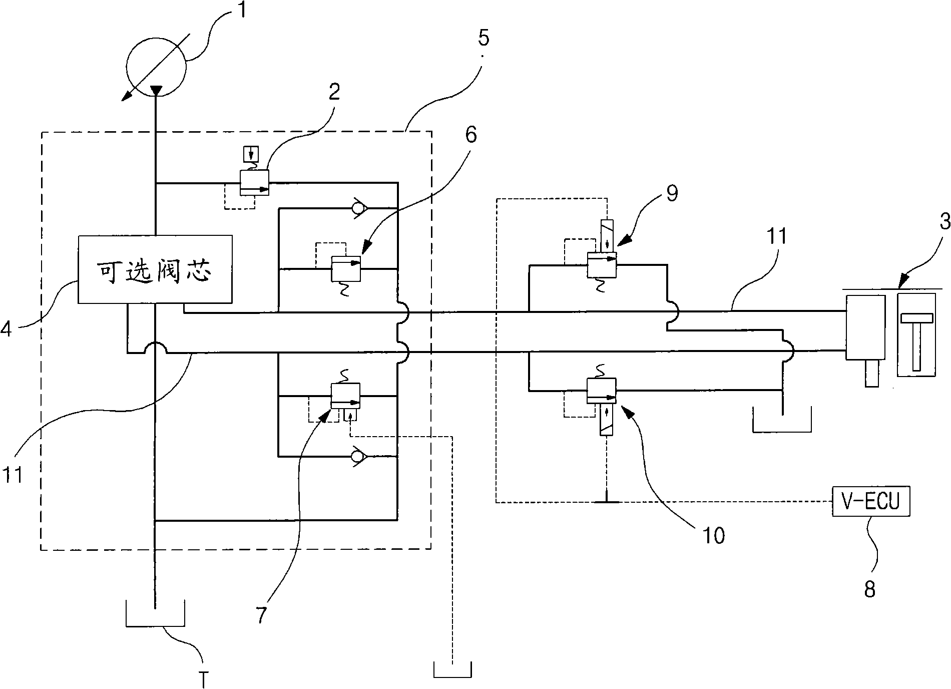
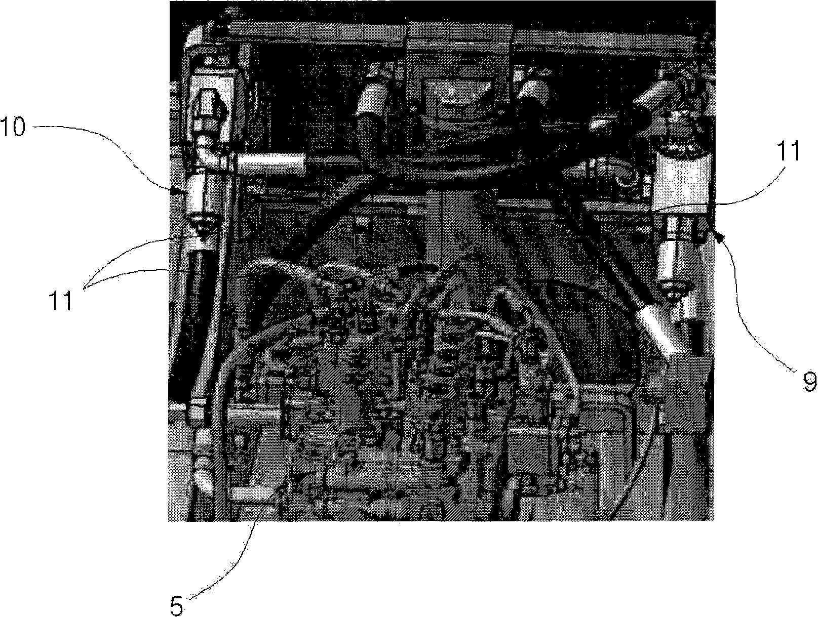
[0006] like figure 1 and figure 2 As shown, according to the conventional hydraulic circuit, since the variable safety valves 9 and 10 are separated from the main control valve 5 to form a separate block, it is used to integrate the main control valve 5, the variable safety valves 9 and 10 and the working equipment The structure of the interconnected hydraulic pipes is complex, which leads to increased costs for manufacturing and assembling the structure
[0007] Furthermore, since the variable safety valves 9 and 10 and the associated pipes, each having the functions of an electronic proportional valve and a safety valve, are connected to the optional line 11, sufficient space for connecting the corresponding valves and the pipes therein cannot be ensured, thereby reducing usability and practicality
[0008] In addition, since the variable safety valves 9 and 10 and related pipes are additionally connected to the optional line 11 provided outside the main control valve 5, the number of corresponding parts increases, thereby also increasing the manufacturing cost.

Method used


Image

  • Hydraulic circuit for heavy equipment having variable control device
  • Hydraulic circuit for heavy equipment having variable control device
  • Hydraulic circuit for heavy equipment having variable control device

Examples


Embodiment Construction

[0019] Hereinafter, preferred embodiments of the present invention will be described with reference to the accompanying drawings. The matters defined in the specification, such as detailed structures and elements, are only provided to provide specific details to help those of ordinary skill in the art fully understand the present invention, and thus the present invention is not limited thereto.

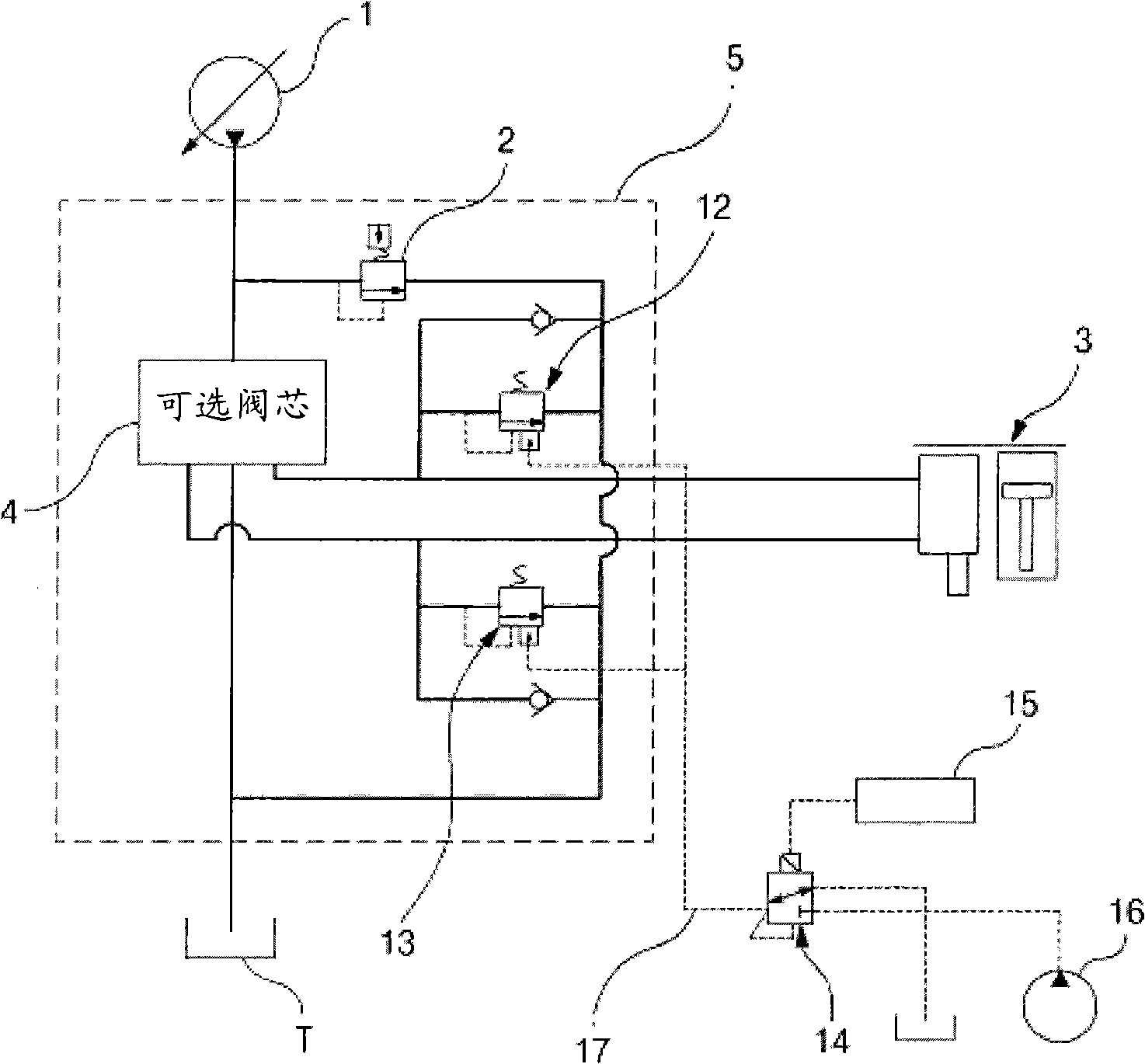
[0020] Such as image 3 and Figure 4 As shown, the hydraulic circuit for heavy equipment with a variable control device according to an embodiment of the present invention includes: at least one variable displacement hydraulic pump 1; a main safety valve 2 installed on the upstream side of the discharge flow path of the hydraulic pump 1, It is used to discharge part or all of the hydraulic fluid to the hydraulic tank T when an overload exceeding a predetermined pressure is generated in this hydraulic circuit; an optional accessory 3 connected to the hydraulic pump 1 (for example, a ...


PUM


Abstract

A hydraulic circuit includes at least one variable displacement hydraulic pump; a main relief valve installed on an upstream side of a discharge flow path of the hydraulic pump; an option attachment connected to the hydraulic pump; a main control valve installed in a flow path between the hydraulic pump and the option attachment; port relief valves, installed inside the main control valve, for being proportionally controlled so as to variably control relief pressure required for the option attachment in accordance with pilot signal pressure inputted from an outside; and a proportional relief valve, installed outside the main control valve, for variably controlling the pilot signal pressure inputted to the port relief valves in accordance with an electric signal inputted from an outside.

Description

technical field [0001] The present invention relates to a hydraulic circuit for heavy equipment with variable control means to variably control the flow rate and operating pressure required for an optional Conditions can optionally be attached to excavators. [0002] More specifically, the present invention relates to a hydraulic circuit for heavy equipment having a variable control device provided with a variable relief valve installed in a main control valve (MCV) having Built-in proportional control function to variably control the operating pressure and flow rate of the optional accessory being replaced, and according to the optional The selection of the working mode variably controls the pressure of the variable safety valve. Background technique [0003] To comprehensively utilize heavy equipment such as an excavator, a bucket may be removed from the heavy equipment, and an optional attachment such as a hammer may be attached to the heavy equipment depending on opera...

Claims


Application Information

Patent Timeline
Patent Type & Authority Applications(China)
IPC IPC(8): F15B13/02F15B11/00E02F9/22
CPCF15B11/028F15B2211/7053F15B2211/5153E02F9/2228F15B2211/5159F15B2211/50518E02F9/2296E02F3/963F15B11/02
Inventor 孙泳进
Owner SAMSUNG HEAVY IND CO LTD
Learn More