
Supporting tool for replacing bearing in auxiliary manner

A technology for auxiliary bearings and tooling, which is applied in the manufacture of tools, transmission parts, hand-held tools, etc. It can solve problems such as bearing damage, affecting the stability of the support, the rotation accuracy of the gear shaft, and the long disassembly cycle.

Pending Publication Date: 2019-12-13
NANJING HIGH SPEED GEAR MFG
View PDF0 Cites 4 Cited by
  • Summary
  • Abstract
  • Description
  • Claims
  • Application Information

AI Technical Summary

Problems solved by technology

Bearings will wear out during long-term use, and the worn bearings will seriously affect their support stability and the rotation accuracy of the gear shaft, so they need to be replaced regularly
[0003] There are generally two ways to replace the existing bearings. The first is to disassemble the gearbox, then take out the parallel shaft system of the gearbox, and then replace the bearing on the gear shaft. However, this method requires unpacking. Not only complex operation but also long disassembly cycle
The second is to use the sling to hang the shafting of the gearbox to replace the bearing, but this method cannot accurately position and stably support the shafting during the bearing replacement process
During the bearing replacement process, the shaft system will inevitably rotate, but because the rotation accuracy and stability of the shaft system cannot be guaranteed, it will cause damage to the gears on the shaft system and the bearing at the other end, thus affecting the performance of the above components Safety during service life and replacement as well as replacement efficiency

Method used


Image

  • Supporting tool for replacing bearing in auxiliary manner
  • Supporting tool for replacing bearing in auxiliary manner
  • Supporting tool for replacing bearing in auxiliary manner

Examples


Embodiment Construction

[0030] The technical solutions of the present invention will be clearly and completely described below in conjunction with the accompanying drawings. Apparently, the described embodiments are some of the embodiments of the present invention, but not all of them. Based on the embodiments of the present invention, all other embodiments obtained by persons of ordinary skill in the art without making creative efforts belong to the protection scope of the present invention.

[0031] In the description of the present invention, it should be noted that the terms "center", "upper", "lower", "left", "right", "vertical", "horizontal", "inner", "outer" etc. The indicated orientation or positional relationship is based on the orientation or positional relationship shown in the drawings, and is only for the convenience of describing the present invention and simplifying the description, rather than indicating or implying that the referred device or element must have a specific orientation, ...


PUM


Abstract

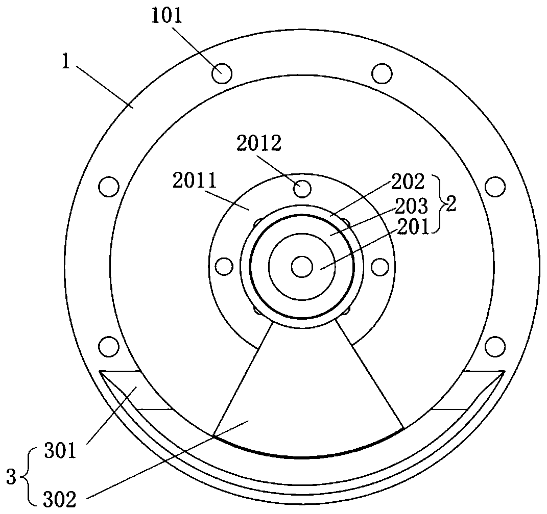
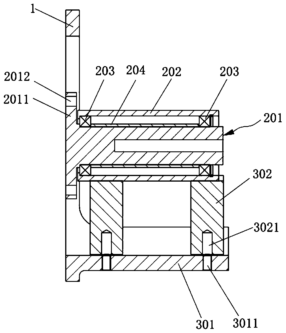
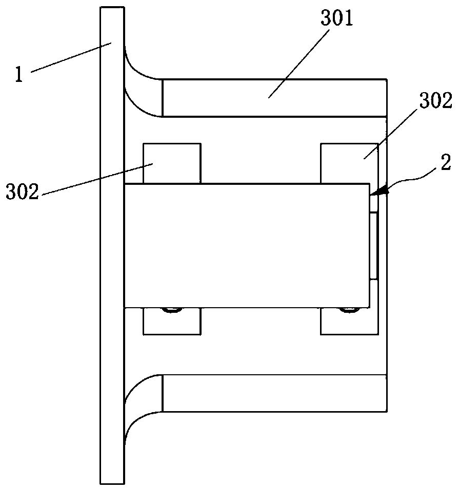
The invention discloses a supporting tool for replacing a bearing in an auxiliary manner and belongs to the technical field of mechanical assembly. The supporting tool comprises a mounting structure,a supporting shaft assembly and a bottom supporting assembly. The supporting shaft assembly comprises a supporting shaft and a bearing pedestal; the bottom supporting assembly comprises a supporting plate and at least two supporting bodies; the supporting bodies are detachably connected between the supporting plate and the bearing pedestal; the supporting bodies are disassembled and assembled between the supporting plate and the bearing pedestal sequentially, so that the bearing can be disassembled and assembled while a gear shaft is supported stably. The supporting tool not only can replace the bearing quickly and conveniently on the premise of not opening a box y matching he supporting shaft assembly with the bottom supporting assembly, but also can support the gear shaft in a gear box stably when the bearing is disassembled and assembled so as to ensure that the gear shaft can rotate freely and has a relatively high rotating precision, so that the gear on the gear shaft and the bearing at the other end are prevented from being damaged, and therefore, the safety of the gearbox is improved.

Description

technical field [0001] The invention relates to the technical field of mechanical assembly, in particular to a support tool for assisting bearing replacement. Background technique [0002] Bearing is a common component in the gearbox, which is mainly used to support the rotation of the gear shaft, so as to reduce the friction force on the gear shaft during the rotation process and improve the rotation accuracy of the gear shaft during the rotation process. Bearings will wear out during long-term use, and the worn bearings will seriously affect their support stability and the rotation accuracy of the gear shaft, so they need to be replaced regularly. [0003] There are generally two ways to replace the existing bearings. The first is to disassemble the gearbox, then take out the parallel shaft system of the gearbox, and then replace the bearing on the gear shaft. However, this method requires unpacking. Not only the operation is complicated but also the disassembly cycle is ...

Claims


Application Information

Patent Timeline
IPC IPC(8): F16H57/00F16H57/021F16H57/023B25B27/14
CPCF16H57/00F16H57/021F16H57/023
Inventor 罗文振许军王福东秦野朱泉生
Owner NANJING HIGH SPEED GEAR MFG
Learn More