A new type of sealing machine

A sealing machine, a new type of technology, applied in packaging sealing/fastening, external support, transportation packaging, etc., can solve problems such as low replacement efficiency, damage to conveyor belts, affecting transmission structure coordination, etc., to achieve easy disassembly and installation, and structural flexibility. High, improve the effect of product quality

Active Publication Date: 2018-07-10
HUALIAN MACHINERY GRP
View PDF8 Cites 2 Cited by
  • Summary
  • Abstract
  • Description
  • Claims
  • Application Information

AI Technical Summary

Problems solved by technology

The transmission structure of the existing sealing machine is fixed, if the sealing belt is worn or loose after long-term use, it will greatly affect the sealing quality of the packaging bag, and the fixed transmission structure is inconvenient to replace the sealing belt. Only when the structure is pressed manually can the sealing tape be removed for replacement, the replacement efficiency is low, which affects production efficiency, and the disassembly process will also affect the cooperation between the transmission structures, and debugging is required to ensure that the sealing tape is installed in parallel and the sealing quality is guaranteed; It is also difficult to adjust whether the sealing belt is parallel or not under the existing technical structure. The inclination of the sealing belt will greatly affect the sealing quality. The method of disassembling the drive wheel is not only cumbersome, but also cannot ensure that a parallel sealing belt can be debugged at one time; The heating mechanism and cooling mechanism on the machine are the core components, and it is cumbersome to replace them after long-term use. Because they are in close contact with the conveyor belt, it is easy to cause damage to the conveyor belt during replacement and affect the service life of the sealing machine.

Method used


Image

  • A new type of sealing machine
  • A new type of sealing machine
  • A new type of sealing machine

Examples


Embodiment 1

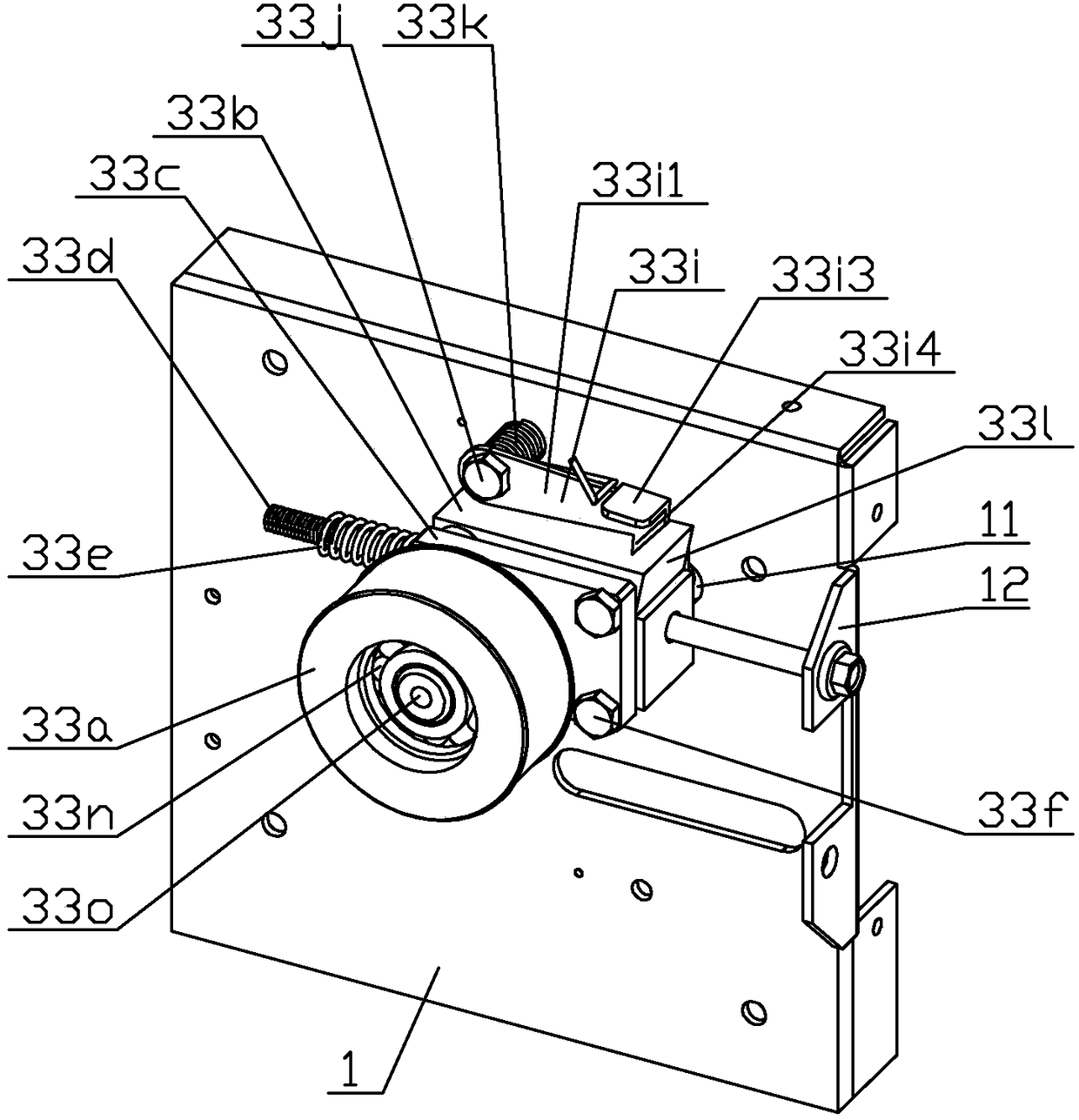
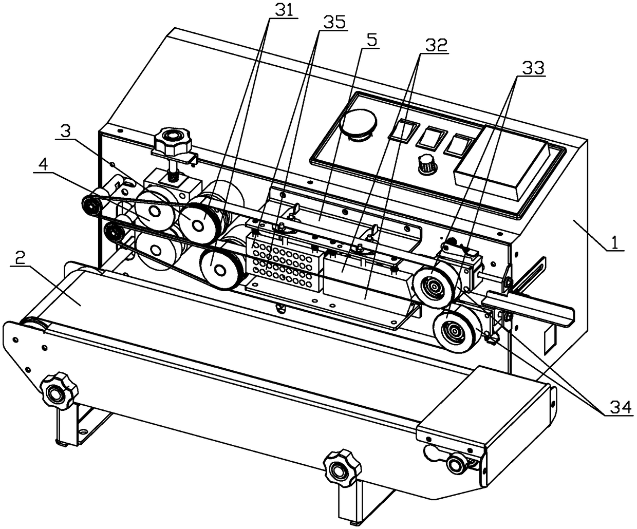
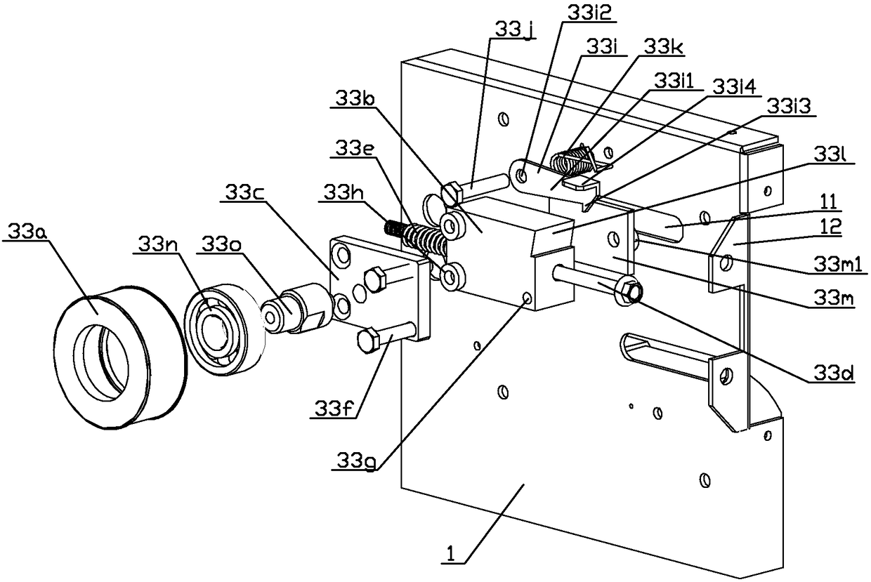
[0024] Such as Figure 1-8Shown is a specific embodiment of the sealing machine of the present invention. This embodiment 1, a new type of sealing machine, including a body 1, a conveying mechanism 2, a sealing mechanism 3 and an embossing mechanism 4, the sealing mechanism 3 and the embossing mechanism 4 are sequentially arranged on the body 1, and the conveying mechanism 2 is located at the bottom of the body 1 The side is arranged in parallel with the sealing mechanism 3 and the embossing mechanism 4. It is characterized in that: the sealing mechanism 3 includes a drive wheel mechanism 31, a heating mechanism 32, a cooling mechanism 35 and a driven wheel mechanism 33 that are symmetrically arranged up and down in groups. The sealing conveyor belt 34 is set on the wheel mechanism 31 and the driven wheel mechanism 33, and the heating mechanism 32 and the cooling mechanism 35 are located between the driving wheel mechanism 31 and the driven wheel mechanism 33 and are wrapped o...


PUM


Abstract

The invention discloses a sealing machine. A driven wheel mechanism of the sealing machine brings convenience for a user to rapidly conducting slide adjustment on an adjusting base in the horizontal direction through the adjusting base arranged on a long screw rod in a penetrating manner, a sealing conveying belt tensioned on a driven wheel body can be rapidly loosened, and disassembling and assembling are facilitated; movement of the adjusting base is limited through elastic force of a compression spring, when the user does not exert force to the adjusting base, the adjusting base is ejected outwards through elastic force of the compression spring, and the sealing conveying belt is tensioned; a structure that the adjusting base and an adjusting plate are matched is arranged, a plurality of sets of screws and screw holes are stably mounted, after extra screws are arranged to eject the adjusting base, if rotation continues, the adjusting plate and the adjusting base are slightly ejected to be open, the angle of the adjusting plate is slightly adjusted, the driven wheel body is kept horizontal, stable conveying of the sealing machine is ensured, and sealing is flat. A heating mechanism and a cooling mechanism are lifted through a structure of a rotary limiting block to be separated from the sealing conveying belt, and the heating mechanism and the cooling mechanism are debugged and replaced conveniently.

Description

technical field [0001] The invention relates to the field of packaging machinery, in particular to a novel sealing machine. Background technique [0002] The sealing machine is the last process of sealing the packaging tape during product processing. It can ensure the sealing of the packaging bag and ensure that the product is well preserved in the packaging bag, and it is not easy to cause product deterioration or product leakage due to air leakage. The transmission structure of the existing sealing machine is fixed, if the sealing belt is worn or loose after long-term use, it will greatly affect the sealing quality of the packaging bag, and the fixed transmission structure is inconvenient to replace the sealing belt. Only when the structure is pressed manually can the sealing tape be removed for replacement, the replacement efficiency is low, which affects production efficiency, and the disassembly process will also affect the cooperation between the transmission structure...

Claims


Application Information

Patent Timeline
Patent Type & Authority Patents(China)
IPC IPC(8): B65B51/10B65B51/32
CPCB65B51/10B65B51/32
Inventor 陈伯贵宋水平陈静蒋琪
Owner HUALIAN MACHINERY GRP
Why Eureka
Try Eureka