Liquid distributor, compressor and air conditioning system
A liquid separator and compressor technology, used in compressors, refrigerators, refrigeration and liquefaction, etc., can solve the problems of compressor energy efficiency and refrigeration capacity reaching a better level, and achieve excellent refrigeration capacity, energy efficiency and good effect. Effect
- Summary
- Abstract
- Description
- Claims
- Application Information
AI Technical Summary
Problems solved by technology
Method used
Image
Examples
Embodiment 1
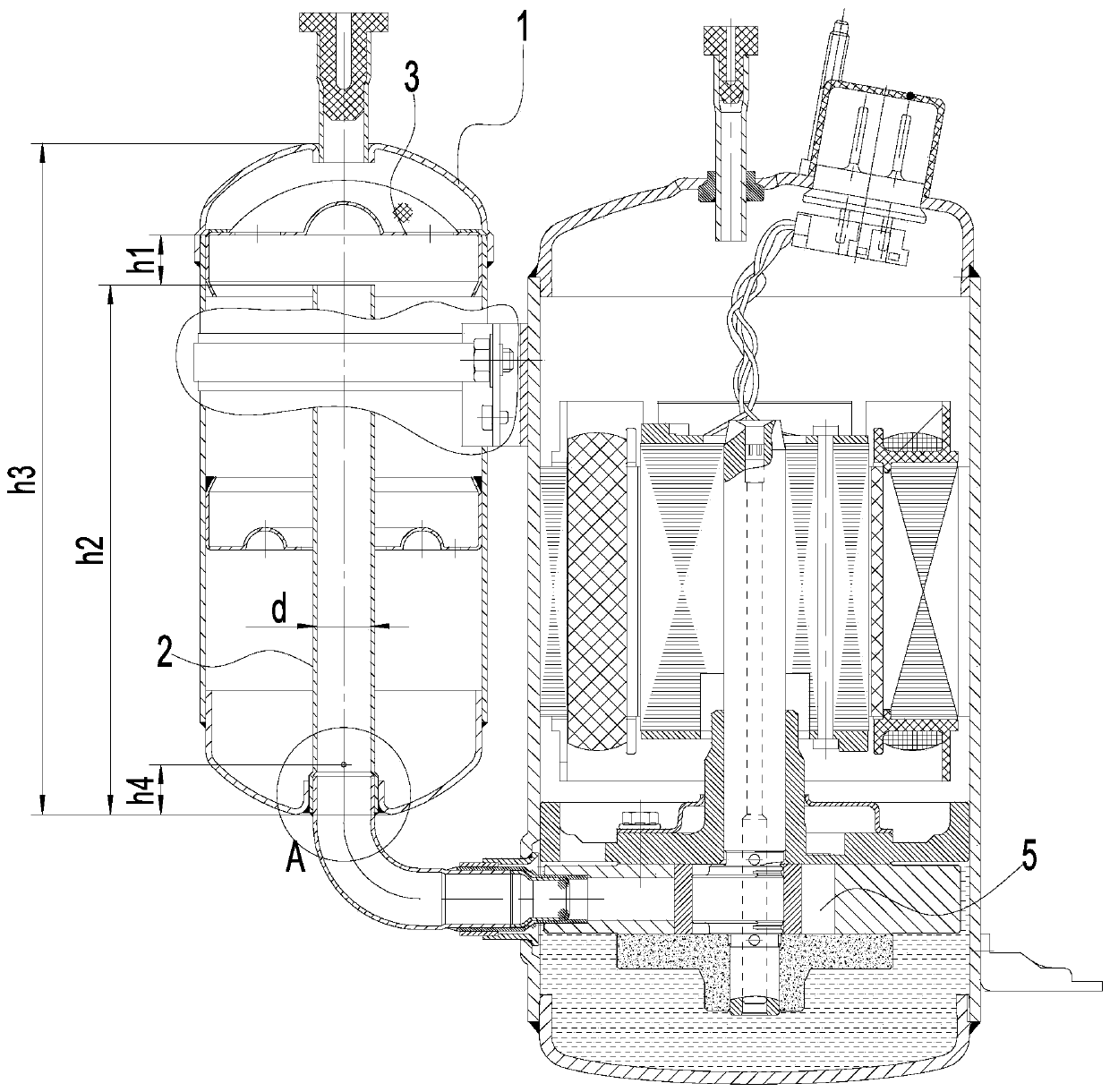
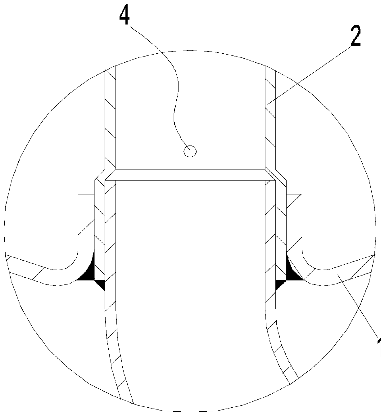
[0034] This embodiment provides a liquid distributor, including a liquid distributor main body 1. A flow channel 2 for circulating refrigerant is provided inside the liquid distributor main body 1. The flow area of the flow channel 2 is defined as S, that is, the flow area is limited. The cross-sectional area of the channel 2 is S, and the working volume of the compressor is limited to V, that is, the working volume of the compression chamber of the cylinder 5 used in the compressor is V, 5≤S / V≤30.
[0035] This design provides a better solution for the selection and manufacture of compressors and liquid separators. The flow area of the internal channel 2 of the liquid separator main body 1 is determined according to the working volume of the compressor and satisfies 5≤S / V≤30, so that the effect of the liquid separator can be better when used with the compressor, so as to improve the energy efficiency (COP) and cooling capacity of the compressor using the liquid separato...
Embodiment 2
[0037] This embodiment is a specific implementation of Embodiment 1. In this embodiment, the number of flow channels 2 in the liquid distributor body 1 is limited to one, so that the compressor used in conjunction with it is a single suction compressor, such as figure 1 As shown, at this time, the ratio of S / V is limited to 10 to 30, that is, 10≤S / V≤30, so that the liquid separator has a better effect, and the single-suction compressor has a higher energy efficiency and cooling capacity.
[0038] The following tabular data can be obtained from experiments and practice, Figure 5 is the variation curve of single suction compressor COP with S / V, Image 6 It is a graph showing the variation of cooling capacity of single-suction compressor with S / V. When 10≤S / V≤30, the COP (energy efficiency) and cooling capacity are at an optimal level, and the COP increases with the increase of the S / V ratio, and the cooling capacity decreases with the increase of the S / V ratio. When S / V30, ...
Embodiment 3
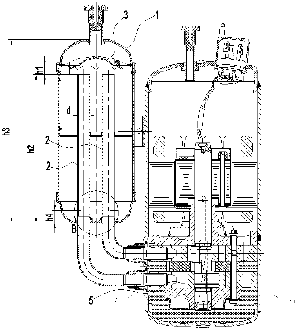
[0040] This embodiment is another specific implementation of embodiment 1. In this embodiment, the number of flow passages 2 in the liquid separator main body 1 is limited to two, so that the compressor used in conjunction with it is a double suction compressor, such as figure 2 As shown, at this time, the ratio of S / V is limited to 5 to 25, that is, 5≤S / V≤25, so that the liquid separator has a better effect, and the single-suction compressor has a higher energy efficiency and cooling capacity.
PUM
 Abstract
Description
Claims
Application Information
 - R&D
- Intellectual Property
- Life Sciences
- Materials
- Tech Scout
- Unparalleled Data Quality
- Higher Quality Content
- 60% Fewer Hallucinations
Browse by: Latest US Patents, China's latest patents, Technical Efficacy Thesaurus, Application Domain, Technology Topic, Popular Technical Reports.
© 2025 PatSnap. All rights reserved.Legal|Privacy policy|Modern Slavery Act Transparency Statement|Sitemap|About US| Contact US: help@patsnap.com


