Blasting fixing device, and draw shaft dredging system and method applied to blasting fixing device
A technology for fixing devices and chute, which is applied in the field of chute unclogging system and blasting fixing device, which can solve the problems of high cost and difficult operation, and achieve the effect of low cost, low cost and obvious effect
- Summary
- Abstract
- Description
- Claims
- Application Information
AI Technical Summary
Problems solved by technology
Method used
Image
Examples
Embodiment 1
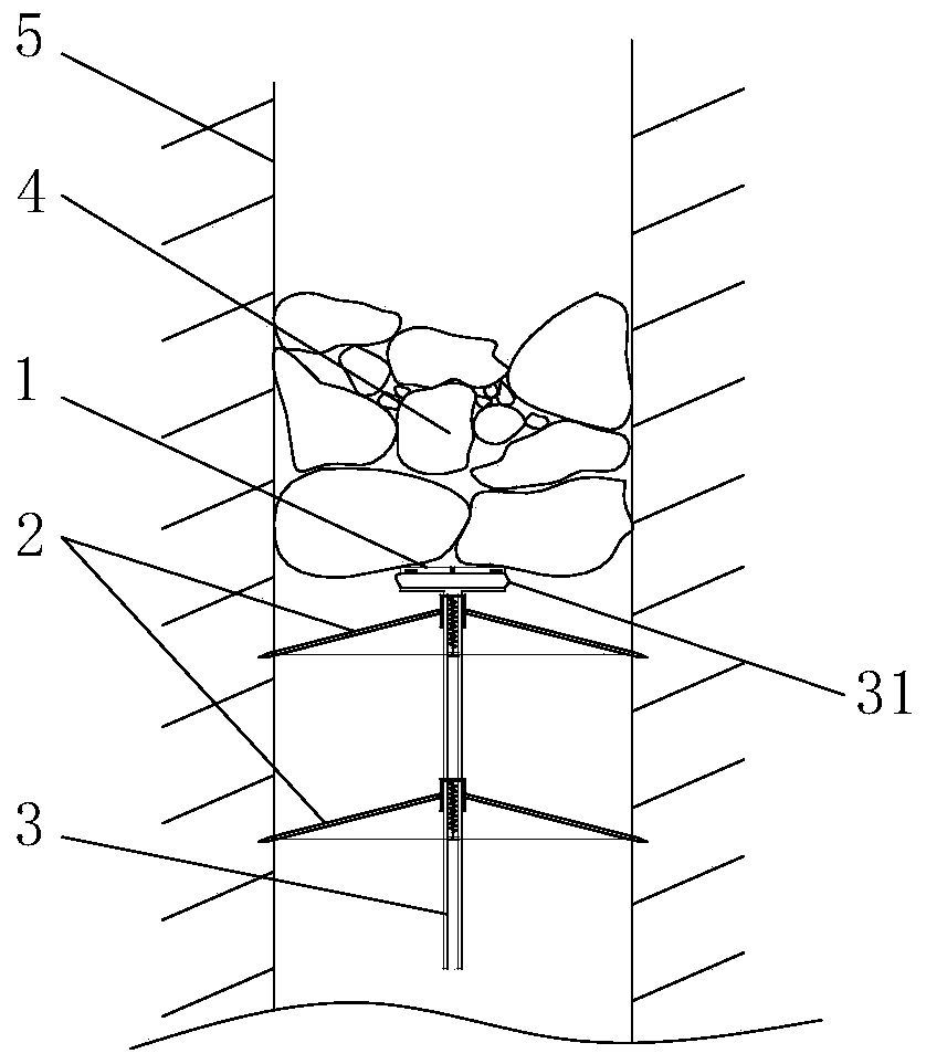
[0040] see figure 1 , the blasting fixing device in the illustration is a specific embodiment of the present invention, which can be used for fixing the explosive package when blasting and clearing the blockage inside the chute channel, and can also be used for fixing the explosive package when blasting inside other channels.
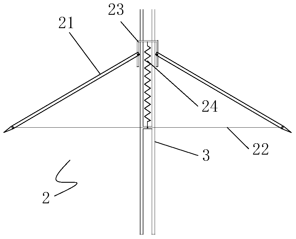
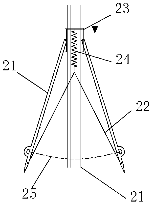
[0041] The blasting fixture of this embodiment includes an umbrella-shaped support mechanism 2 and a vertical pole 3, wherein the vertical pole 3 is the axis skeleton of the entire blasting fixture, and the top of the vertical pole 3 is provided with a support platform 31 for placing the explosive package 1. The support mechanism 2 is set on the vertical pole 3, and the explosive package 1 is arranged on the top of the entire blasting fixture. After the explosive package 1 is attached to the blockage 4 to be blasted, the umbrella-shaped support mechanism 2 that forms a forward conical support structure The entire blasting fixture and the explosive packa...
Embodiment 2
[0049] see Figure 5 The chute dredging system disclosed in this example is a further application implementation of the blasting fixture in Example 1. On the basis of the blasting fixture in Example 1, this example further provides a blasting fixture and an explosive The package is moved and transported to the lifting device 6 at the high-level blockage in the vertical chute, the entire blasting fixture is placed on the lifting device 6, and the lifting device 6 is set on the downcomer 51 below the blockage in the chute through the telescopic bottom plate 61 that stretches in the horizontal direction Inside, the telescopic bottom plate 61 can be extended and retracted through guide rails and electric telescopic rods or hydraulic telescopic rods. The extended telescopic bottom plate 61 extends the lifting device 6 and the blasting fixing device placed on it from the downcomer 51 to the chute 52. internal.
[0050] see in conjunction Figure 6 , the lifting device 6 in the pre...
Embodiment 3
[0053] Considering the irregularity of the inner wall of the mine channel, all the diagonal struts 21 in the umbrella support mechanism of the blasting fixture may not be able to fully support the inner wall of the channel. This embodiment provides another specific implementation of the blasting fixture to fix the problem.
[0054] see in conjunction figure 1 as well as Figure 7 and Figure 8 , the ends of the diagonal struts 21 of the umbrella support mechanism 2 in the present embodiment are fixed and hinged on the independent sliders 26, and one diagonal strut 21 corresponds to one slider 26, and the vertical rod 3 is provided along the axial direction for The sliding block 26 is an annular slideway for axial sliding, and several groups of corresponding diagonal struts 21 are arranged on the outer circumference of the vertical rod 3 to connect the sliding grooves 33 of the sliding blocks 26, and all the sliding blocks 26 connected to the diagonal struts 21 pass through t...
PUM
 Abstract
Description
Claims
Application Information
 - R&D
- Intellectual Property
- Life Sciences
- Materials
- Tech Scout
- Unparalleled Data Quality
- Higher Quality Content
- 60% Fewer Hallucinations
Browse by: Latest US Patents, China's latest patents, Technical Efficacy Thesaurus, Application Domain, Technology Topic, Popular Technical Reports.
© 2025 PatSnap. All rights reserved.Legal|Privacy policy|Modern Slavery Act Transparency Statement|Sitemap|About US| Contact US: help@patsnap.com


