Flowmeter calibration system with multiple calibration lines and calibration method based on system

A technology for calibrating system and flowmeter, applied in the field of multi-calibration line flowmeter calibration system, can solve problems such as high cost and low calibration efficiency

Pending Publication Date: 2019-12-13
CHONGQING WECAN PRECISION INSTR
View PDF0 Cites 1 Cited by
  • Summary
  • Abstract
  • Description
  • Claims
  • Application Information

AI Technical Summary

Problems solved by technology

[0003] The above several calibration methods are carried out in the laboratory, but the traditional laboratory water meter ca

Method used


Image

  • Flowmeter calibration system with multiple calibration lines and calibration method based on system
  • Flowmeter calibration system with multiple calibration lines and calibration method based on system
  • Flowmeter calibration system with multiple calibration lines and calibration method based on system

Examples


Embodiment 1

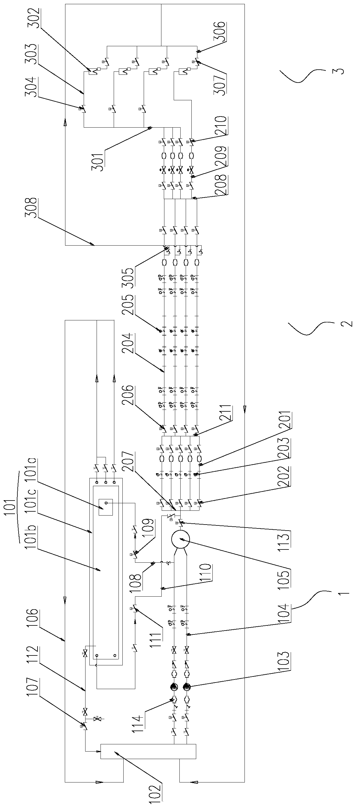
[0050] Example 1, such as figure 1 As shown, a flow meter calibration system with multiple calibration lines includes a water supply mechanism 1 and a calibration mechanism 2;

[0051] The water supply mechanism 1 includes a reservoir 102. The reservoir 102 is connected with L first water supply pipes 104, where L is a natural number. The water outlet ends of all the first water supply pipes 104 are connected to the same surge tank 105. A water pump 103 is installed on a water supply pipe 104;

[0052] The calibration mechanism 2 includes P standard tubes 201 connected in parallel. P is an integer greater than or equal to 2. The water inlet ends of all standard tubes 201 are connected to the surge tank 105, and the standard tube 201 is equipped with a standard tube control Valve 201 and standard flow meter 203. The water outlet ends of all standard pipes 201 are connected to the same first manifold 211. The first manifold 211 is connected to at least two calibration tubes 204, and...

Embodiment 2

[0069] Embodiment 2, a calibration method based on embodiment 1, is carried out in the following steps:

[0070] S1 Set calibration line: select any one of the calibration tubes 204 as the line to be calibrated, open the calibration tube control valve 206 on the selected calibration tube 204 to make it in the path state, and close the other calibration tube control valves 206 , The flow meter to be checked 205 has i flow to be calibrated, denoted as Q i ,i=1,2,3...n 1 , Choose any Q i For calibration, there are generally 4 flows to be checked, which are Q 1 Minimum flow, Q 2 Boundary flow, Q 3 Common flow, Q 4 Overload flow, all flow units are m 3 / h;

[0071] S2 Select the water supply mode: Count the maximum water supply flow Q of the K first water supply pipes 104 connected to the water supply pipe 108 KP

[0072]

[0073] Among them, Q pupm,p -Pump flow of water pump, m 3 / h;

[0074] If Q KP ≥Q i , Then open the water supply control valve 109, the second water supply switch 111...


PUM


Abstract

The invention discloses a flowmeter calibration system with multiple calibration lines and a calibration method based on the system. The system comprises a water supply mechanism and a calibration mechanism, wherein the calibration mechanism comprises at least two standard tubes, all the standard tubes are connected with the water supply mechanism, a standard tube control valve and a standard flowmeter are installed on each standard tube, the water-out ends of all the standard tubes are connected with the same first converging tube, the first converging tube is connected with at least two calibration tubes, N to-be-detected flowmeters are connected in series on each calibration tube, a calibration tube control valve is also installed on each calibration tube, and all the calibration tubesare connected with the same flow regulation mechanism. According to the system, multiple calibration tubes are adopted and connected in parallel, multiple to-be-detected flowmeters are installed on each calibration tube, multiple to-be-detected flowmeters can be calibrated at a time when one arbitrary calibration tube is opened separately, different flowmeters can be calibrated when different calibration tubes are opened respectively, therefore, assembly-line calibration of the flowmeters is realized, and calibration time is greatly saved.

Description

Technical field [0001] The invention relates to the technical field of flow meter calibration, in particular to a flow meter calibration system with multiple calibration lines and a calibration method based on the system. Background technique [0002] The water meter must be calibrated before leaving the factory, and can only leave the factory after being qualified. The existing calibration methods include volumetric method, weighing method and standard flowmeter method. The volumetric method is to use the calibration equipment to discharge the water with a constant instantaneous flow rate and enter the standard container after passing the water meter to be calibrated. After a period of time, the value of the water meter and the standard container are compared. The weighing method uses an electronic scale to convert the weighed weight into the volume of water, and then compare it with the reading of the water meter. The standard flow meter method is to compare a standard flow me...

Claims


Application Information

Patent Timeline
IPC IPC(8): G01F25/00
CPCG01F25/14
Inventor 杨劲松李星来
Owner CHONGQING WECAN PRECISION INSTR
Why Eureka
Try Eureka