Display device and driving method thereof

A technology of a display device and a driving method, which is applied in the directions of identification devices, static indicators, optics, etc., and can solve problems such as failure to display display unit areas, visual fragmentation, and affecting user experience, so as to solve visual fragmentation and ensure light transmittance , Improve the effect of innate process yield

Inactive Publication Date: 2019-12-13
WUHAN CHINA STAR OPTOELECTRONICS TECH CO LTD
View PDF4 Cites 16 Cited by
  • Summary
  • Abstract
  • Description
  • Claims
  • Application Information

AI Technical Summary

Problems solved by technology

[0003] The present invention provides a display device to solve the technical problem that in the existing display unit, the area corre

Method used


Image

  • Display device and driving method thereof
  • Display device and driving method thereof
  • Display device and driving method thereof

Examples


Embodiment Construction

[0041] The following descriptions of the various embodiments refer to the accompanying drawings to illustrate specific embodiments in which the invention may be practiced. The directional terms mentioned in the present invention, such as [top], [bottom], [front], [back], [left], [right], [inside], [outside], [side], etc., are only for reference The orientation of the attached schema. Therefore, the directional terms used are used to illustrate and understand the present invention, but not to limit the present invention. In the figures, structurally similar elements are denoted by the same reference numerals.

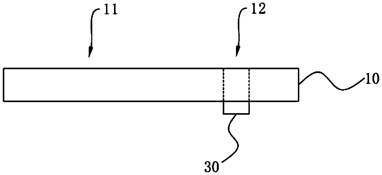
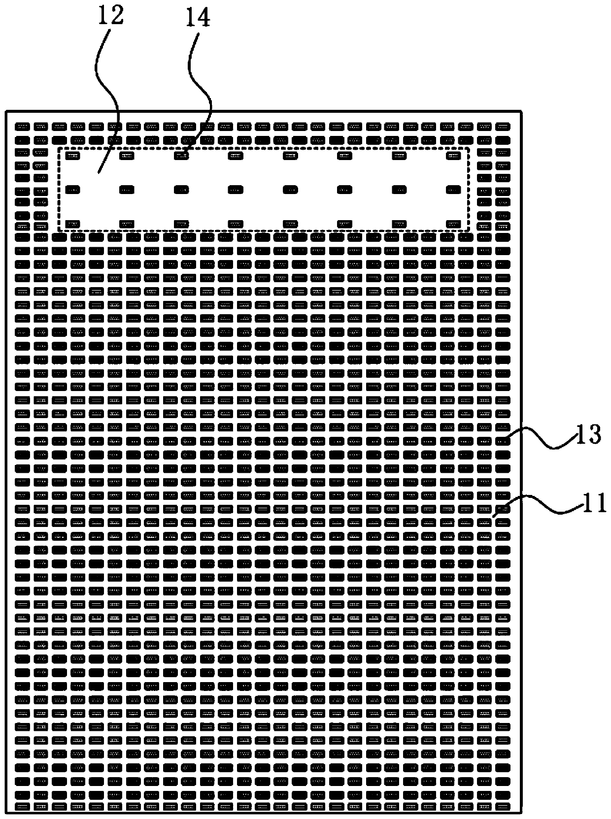
[0042] The present invention aims at that in the existing display unit, the area corresponding to the optical sensor on the display unit cannot be displayed, thus causing visual fragmentation and affecting user experience. The present invention can solve the above-mentioned problems.

[0043] A display device such as Figure 1 to Figure 3 As shown, the display device...


PUM


Abstract

The invention provides a display device. The display device comprises a display unit and a driving module used for driving the display unit to display. The display unit comprises a main display area and at least one display light-transmitting area, a plurality of first sub-pixels are arranged in the main display area, and a plurality of second sub-pixels are arranged in the display light-transmitting area; each second sub-pixel comprises at least one micro light emitting diode. The micro light emitting diodes are arranged in the display light-transmitting area for transparent display, so thatthe light transmittance of the display light-transmitting area is ensured, influence on lighting of functional devices such as a camera is prevented, and the display light-transmitting area can also be used for displaying pictures, so that the display unit realizes full-screen display, and the user experience is improved.

Description

technical field [0001] The present invention relates to the field of display technology, in particular to a display device and a driving method thereof. Background technique [0002] With the popularity of full-screen mobile phones and consumers' pursuit of body integration, under-screen sensing technology has become the focus of development in the industry. Because the traditional LCD is passively illuminated by the entire backlight, the optical sensor and the optical display cannot overlap in space. The area corresponding to the optical sensor on the display unit cannot be displayed, resulting in visual fragmentation and affecting user experience. Contents of the invention [0003] The present invention provides a display device to solve the technical problem that in the existing display unit, the area corresponding to the optical sensor on the display unit cannot be displayed, resulting in visual fragmentation and affecting user experience. [0004] In order to solve ...

Claims


Application Information

Patent Timeline
IPC IPC(8): G02F1/1333G09F9/33G09G3/36G09G3/32
CPCG02F1/1333G09F9/33G09G3/32G09G3/36G02F1/133388
Inventor 钟莉查国伟
Owner WUHAN CHINA STAR OPTOELECTRONICS TECH CO LTD
Why Eureka
Try Eureka