Combined secondary imaging vision light source

A secondary imaging, combined technology, applied in the field of light sources, can solve problems such as unfavorable image processing and inability to obtain high-quality images.

Pending Publication Date: 2019-12-13
WAVE CREST SHANGHAI
View PDF0 Cites 3 Cited by
  • Summary
  • Abstract
  • Description
  • Claims
  • Application Information

AI Technical Summary

Problems solved by technology

The secondary imaging visual light source used in this co-optical axis alignment system does not capture the marking points of the upper object 10 and

Method used


Image

  • Combined secondary imaging vision light source
  • Combined secondary imaging vision light source
  • Combined secondary imaging vision light source

Examples


Embodiment Construction

[0017] The present invention will be further described below in conjunction with the accompanying drawings and specific embodiments.

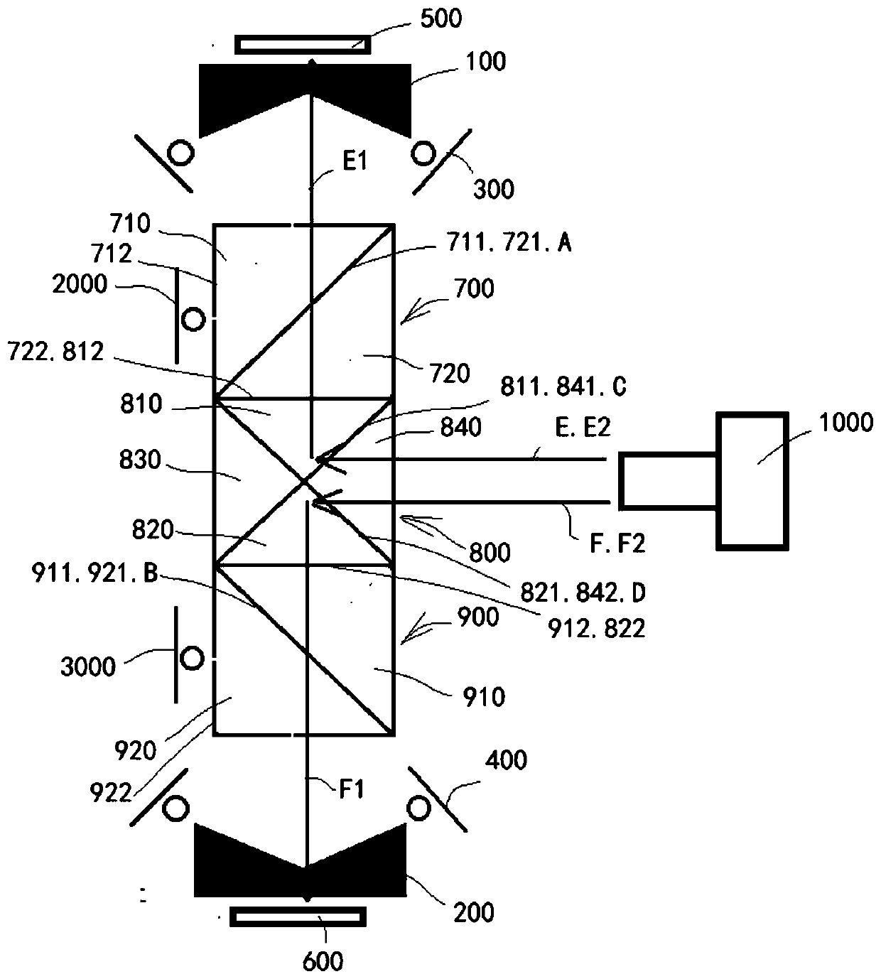
[0018] see image 3 , a combined secondary imaging visual light source for the optical axis alignment system, including an upper concave lens 100, a lower concave lens 200, an upper ring light source 300, and a lower ring light source 400. The upper concave lens 100 is located above the upper ring light source 300, and the lower concave lens 200 Located below the lower ring light source 400 , during measurement, the upper object 500 is located above the upward concave lens 100 , and the lower object 600 is located below the upward concave lens 200 .

[0019] The present invention is characterized in that it also includes an upper double-glued right-angle prism 700 , a square prism 800 , and a lower double-glued right-angle prism 900 located between the upper ring light source 300 and the lower ring light source 400 and stacked sequentially from...


PUM


Abstract

The invention provides a combined secondary imaging vision light source which comprises upper and lower concave lenses, upper and lower ring light sources, an upper double-glueed right-angle prism, aquadruple prism and a lower double-glueed right-angle prism, wherein the upper double-glueed right-angle prism, the quadruple prism and the lower double-glueed right-angle prism are located between the upper and lower ring light sources and successively superimposed from top to bottom. When measuring is carried out, the light path of an upper object above the upper concave lens passes through theupper concave lens and the upper double-glueed right-angle prism, directly comes into the quadruple prism, is refracted at right angle by the upper refracting surface in the quadruple prism, directlypasses through the quadruple prism, and then directly comes into an imaging camera for imaging. The light path of a lower object below the lower concave lens passes through the lower concave lens andthe lower double-glueed right-angle prism, directly comes into the quadruple prism, is refracted at right angle by the lower refracting surface in the quadruple prism, directly passes through the quadruple prism, and then directly comes into the imaging camera for imaging. According to the invention, the light paths of the quadruple prism are used; optical path difference is prevented; and the imaging quality of the upper object and the lower object is completely consistent.

Description

technical field [0001] The invention relates to the field of light source technology, in particular to a combined secondary imaging visual light source for a co-optical axis alignment system. Background technique [0002] The high-precision alignment system needs to coordinate the positioning of the 2 objects that need to be aligned, and the accuracy requirements are quite high. It is hoped that the shooting of the upper and lower marking points can be completed under the same optical axis, which requires a high-precision optical path system. At the same time, the materials of the objects to be aligned will vary, and a corresponding light source system is required to obtain high-quality images. [0003] see figure 1 , a secondary imaging visual light source for a coaxial alignment system shown in the figure, including an upper concave lens 1, an upper ring light source 2, an upper right-angle prism 3, a lower right-angle prism 4, a lower ring light source 5, and a lower co...

Claims


Application Information

Patent Timeline
IPC IPC(8): G03B15/03
CPCG03B15/03
Inventor 邵幼平童雷
Owner WAVE CREST SHANGHAI
Why Eureka
Try Eureka