Transmission type image slicer device and working system thereof

A working system and transmissive technology, applied in the fields of astronomical optics, optics, and spectroscopy, it can solve the problems of optical performance defects, different optical paths of segmented images, and difficulty in processing segmented image data.

Inactive Publication Date: 2020-12-18
NANJING INST OF ASTRONOMICAL OPTICS & TECH NAT ASTRONOMICAL OBSE
View PDF4 Cites 1 Cited by
  • Summary
  • Abstract
  • Description
  • Claims
  • Application Information

AI Technical Summary

Problems solved by technology

[0004] The purpose of the present invention is in order to solve 3 technical problems of the image slicer in the field of astronomical spectrum application: (1) the classic reflective image slicer has the optical performance defect that the optical path is different between the sliced ​​images; (2) ) The relevant transmissive image sp

Method used


Image

  • Transmission type image slicer device and working system thereof
  • Transmission type image slicer device and working system thereof
  • Transmission type image slicer device and working system thereof

Examples


Embodiment 1

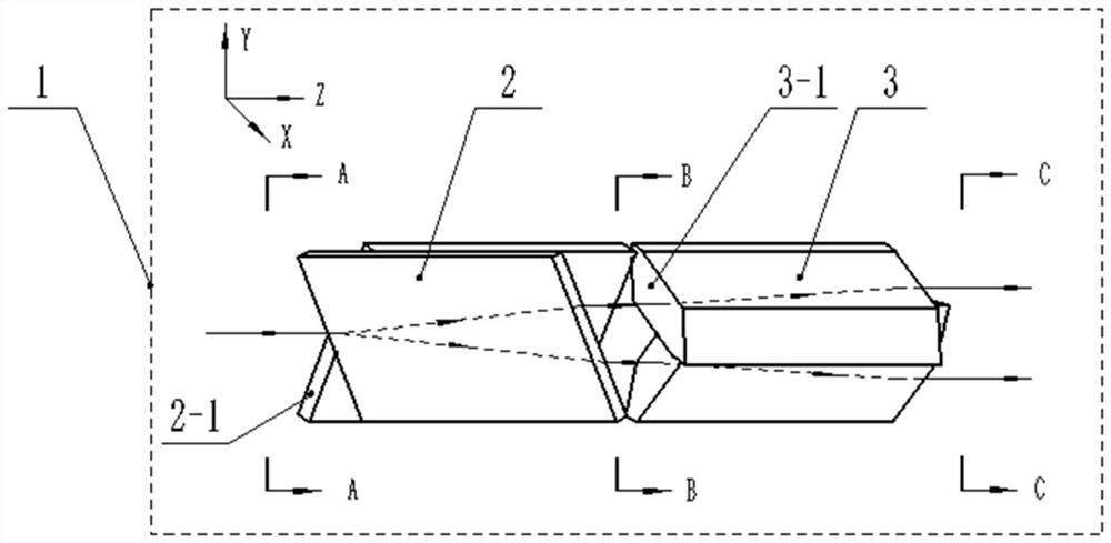
[0028] This embodiment provides a figure 1 The transmissive image splitter device 1 shown includes a front optical unit 2 and a rear optical unit 3 arranged in series along the optical axis direction (Z). in:

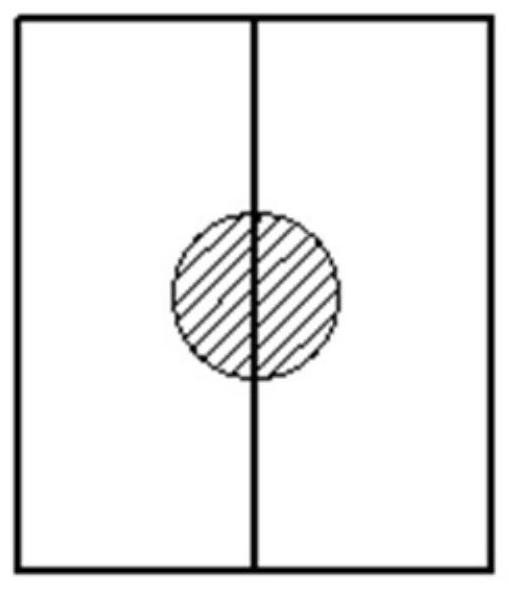
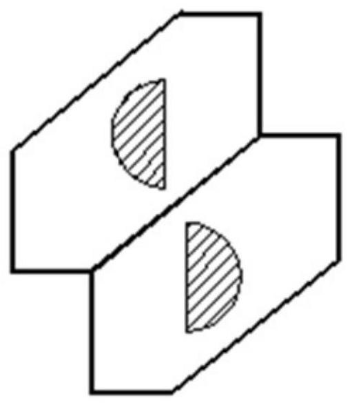
[0029] The front optical unit 2 includes a front first optical element and a front second optical element connected sideways. In this embodiment, the front first optical element and the front second optical element are preferably two identical rhombic prisms , the front side optical unit is set opposite to each other by two rhombic prisms. The front ends of the two rhombic prisms are all inclined first surfaces 2-1, the light beam is incident from the first surface 2-1, and the normal directions of the first surfaces 2-1 of the two rhombic prisms are opposite, forming a certain The included angle, the edges of the connected sides of the rhombic prism are used as a tool for segmenting the image spot. The function of the front optical unit 2 is to segment the image spo...

Embodiment 2

[0040] This embodiment provides a Figure 5 The transmissive image slicer array device shown includes several transmissive image slicer devices 1 sequentially connected along the spatial direction (Y), and several transmissive image slicer devices 1 are neatly stacked to form an array along this direction . In this way, the purpose of separately segmenting and rearranging several linearly arranged image spots is achieved.

[0041] Here, the names of each surface of the transmissive image slicer device 1 can be firstly defined, which are divided into front surface, rear surface, upper surface, lower surface, left side, and right side. The front surface is the slope on which the beam is incident, and the back surface is the slope on which the beam exits; the normal directions of the upper and lower surfaces are parallel to the spatial direction; the normal directions of the left and right sides are parallel to the splitting direction. When multiple transmissive image splitter ...

Embodiment 3

[0044] This embodiment provides a Figure 5 The transmission-type image splitter array working system shown includes a front optical system 4, a turning mirror system 5, and a transmission-type image splitter device 1 (when a single transmission-type image splitter device 1 is used) arranged in sequence along the optical axis direction (Z). During splitter device 1, correspondingly, front optical system 4 only needs to comprise a front optical unit, and turning mirror system 5 also only needs to comprise a turning mirror) or comprise a plurality of transmissive image splitter devices 1 Transmissive image slicer array device (this embodiment specifically uses such as Figure 5 The transmissive image slicer array device shown is taken as an example for illustration), the follow-up optical system 6 . in:

[0045] The front optical system 4 includes several front optical units, these front optical units are sequentially connected along the spatial direction (Y), and are used to ...


PUM


Abstract

The invention discloses a transmission type image slicer device and a working system thereof. The device comprises a front-side optical unit and a rear-side optical unit which are arranged in series in the optical axis direction, the front-side optical unit comprises two optical elements with opposite side faces, the two optical elements are each provided with an inclined first surface, the normaldirections of the two first surfaces are opposite, and the rear-side optical unit comprises two optical elements with the side faces connected; the two optical elements are each provided with an inclined second surface, the normal directions of the two second surfaces are opposite, the image spot is segmented into a plurality of segmented images on the first surface, and the staggered segmented images are linearly rearranged in the space direction through the second surfaces. According to the invention, equal light beam propagation paths are provided for a plurality of segmented images, so the plurality of segmented images are ensured not to have optical path difference; the problem that data processing is difficult due to the fact that the segmented images are staggered in the segmentation direction is solved; the device can be stacked into an array device in the space direction, and the similar array type application requirements of astronomical multi-target optical fiber spectrometers and the like are met.

Description

technical field [0001] The invention belongs to the field of optical technology, in particular to the field of astronomical optics technology and spectrum technology, and specifically relates to an image slicer device and a working system thereof. Background technique [0002] When carrying out astronomical spectral observations on the ground, starlight converges at the slit of the spectrometer, and after passing through the slit, it is dispersed to form a spectrum with a certain resolution. In order to improve the spectral resolution, it is often necessary to make the width of the slit narrower than the diameter of the star image, resulting in most of the light being blocked outside the slit and not being utilized. The image slicer device is to divide the star image into several sliced ​​images with the same width as the slit along the width direction of the slit, and arrange them along the length direction of the slit, so that most of the starlight can enter the spectromet...

Claims


Application Information

Patent Timeline
IPC IPC(8): G02B27/10
CPCG02B27/106
Inventor 张凯朱永田季杭馨王磊
Owner NANJING INST OF ASTRONOMICAL OPTICS & TECH NAT ASTRONOMICAL OBSE
Why Eureka
Try Eureka