a switch device

A switch device and switch technology, applied in the direction of electric switches, electric components, circuits, etc., can solve the problems of poor stability of electric switches

Active Publication Date: 2021-04-16
ZHEJIANG IND & TRADE VACATIONAL COLLEGE
View PDF13 Cites 0 Cited by
  • Summary
  • Abstract
  • Description
  • Claims
  • Application Information

AI Technical Summary

Problems solved by technology

[0003] The purpose of the present invention is to provide a switch device, which solves the defect of poor stability of the traditional electrical switch after conduction locking

Method used


Image

  • a switch device
  • a switch device
  • a switch device

Examples


Embodiment Construction

[0028] The embodiments of the present invention will be described in detail below with reference to the accompanying drawings, but the present invention can be implemented in many different ways defined and covered by the claims.

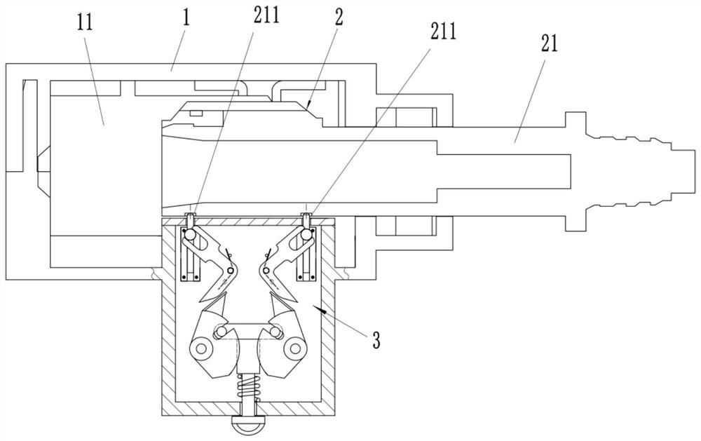
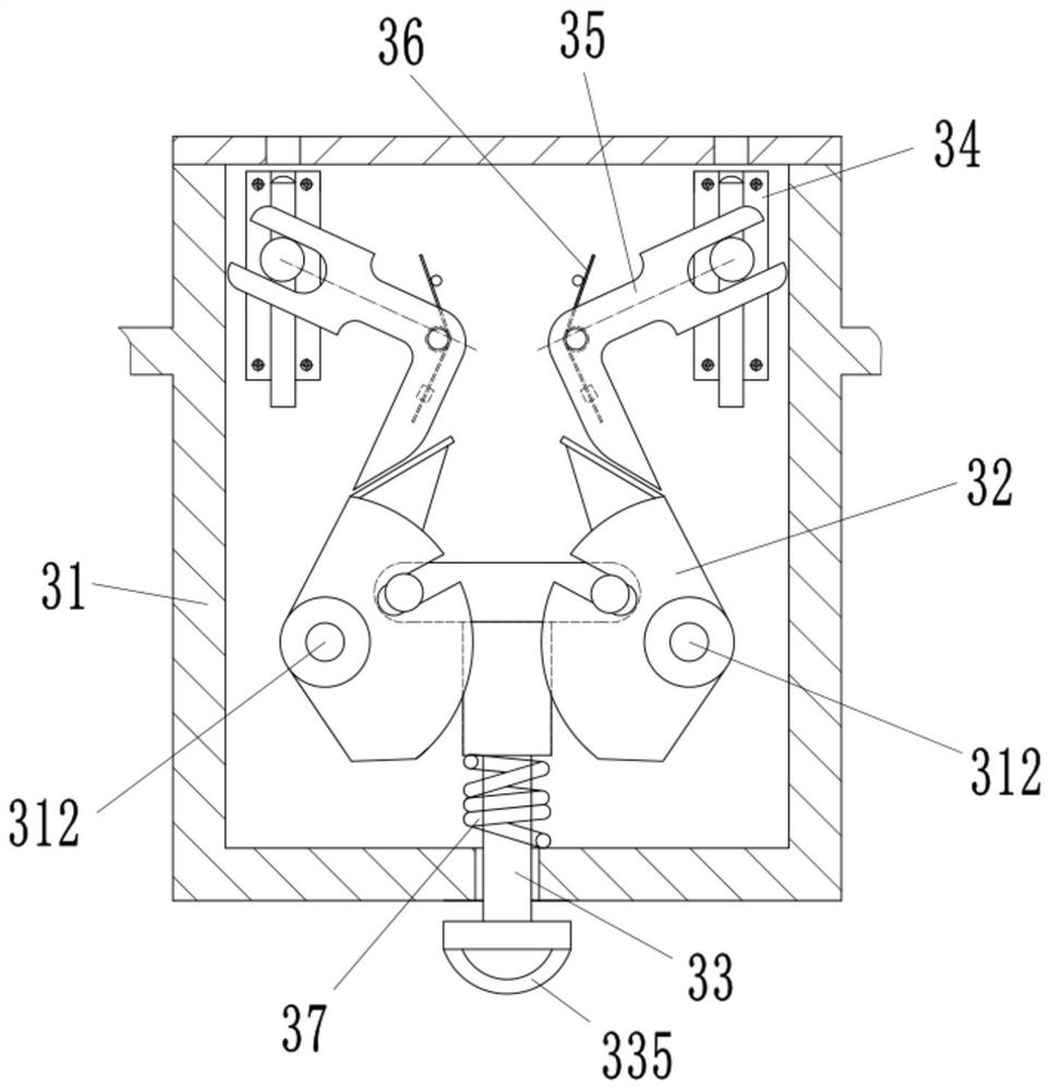
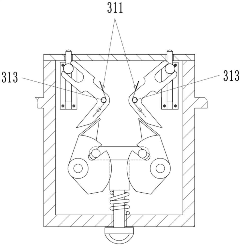
[0029] Refer below Figure 1 to Figure 7 To further explain this application, such as figure 1 The switch device shown includes: a switch housing 1, a push rod assembly 2 and a locking mechanism 3, the switch housing 1 has an accommodating cavity 11, and the push rod 21 of the push rod assembly 2 is slidably arranged on the One end of the accommodating cavity 11, the locking mechanism 3 is arranged on one side of the switch housing 1, the locking mechanism 3 prevents the push rod 21 from sliding out of the accommodating cavity 11, and the locking mechanism 3 includes The protective case 31 connected to the switch housing 1 rotates a pair of fan-shaped wheel plates 32 arranged in the protective case 31 , and extends out of the protective case 31 and...


PUM


Abstract

The present application provides a switch device, including: a switch housing, a push rod assembly and a locking mechanism, the switch housing has an accommodation chamber, the push rod of the push rod assembly is slidably arranged at one end of the accommodation chamber, the The locking mechanism is arranged on one side of the switch housing, and the locking mechanism prevents the push rod from sliding out of the accommodating cavity. A pair of fan-shaped wheel plates in the protective case, a driving member that extends out of the protective case and drives the pair of sector-shaped wheel plates to rotate relatively, two stop seats arranged in the protective case, and pivotally connected to the A pair of linkage frames in the protective shell, wherein a pair of fan-shaped wheel plates respectively move a pair of linkage frames to rotate, and a pair of linkage frames respectively push the stop rods in the two stop seats, so that the stop rods Extending the protective shell against the side of the push rod. The switch device provided by the present application solves the defect of poor stability after conduction locking of the traditional electrical switch.

Description

technical field [0001] The invention relates to the field of electrical control equipment, in particular to a switch device. Background technique [0002] The switch is one of the most common electrical products in daily life. When in use, the closing or opening of the static and dynamic contacts is realized by the action of the button, so as to achieve conduction or disconnection. When the switch is turned on, the circuit controlled by the switch In the closed state, the current can flow through the electrical equipment controlled by the switch. When the electrical equipment operates, after the switch is disconnected, the circuit is in an open state, and the electrical equipment stops operating immediately. Some switches require a conduction lock function, that is, when the switch conducts After it is turned on, it is locked to keep the switch in the on state. The existing locking mechanism of the switch with the function of conducting and locking is generally composed of ...

Claims


Application Information

Patent Timeline
Patent Type & Authority Patents(China)
IPC IPC(8): H01H13/62
CPCH01H13/62
Inventor 温作锐
Owner ZHEJIANG IND & TRADE VACATIONAL COLLEGE
Why Eureka
Try Eureka