Shockproof switch cabinet

An anti-vibration switch and external cabinet technology, which is applied in the direction of anti-vibration equipment, substation/distribution device casing, etc., can solve the problems of poor practicability, too simple shock absorption method, and reduce the shock absorption effect of the shock absorbing device, so as to achieve the shockproof effect. Good, reduce vibration, good shockproof effect

Inactive Publication Date: 2019-12-13
禹州市冠莎科技有限公司
View PDF0 Cites 2 Cited by
  • Summary
  • Abstract
  • Description
  • Claims
  • Application Information

AI Technical Summary

Problems solved by technology

However, the traditional switchgear has a shock absorption method that is too simple, and only uses a shock absorbing spring for shock absorption, and generally only sets the shock absorbing spring at the bottom, which reduces the shock absorbing effect of the shock absorbing device and reduces the practicality. Therefore, it is necessary to provide a shockproof switchgear with simple structure, multi-directional shockproof, good shockproof effect, good stability and strong practicability

Method used


Image

  • Shockproof switch cabinet
  • Shockproof switch cabinet

Examples


Embodiment 1

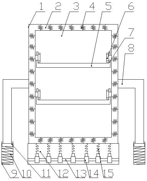
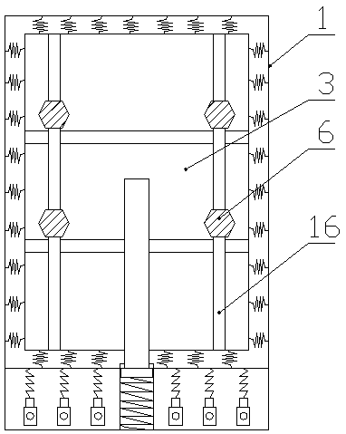
[0016] Such as figure 1 , figure 2 As shown, a kind of anti-vibration switchgear, it comprises outer cabinet body 1 and inner cabinet body 3, the cabinet body gap 2 is formed between described outer cabinet body 1 and inner cabinet body 3, the inner cabinet body gap 2 etc. The first springs 4 are arranged at intervals, the side of the outer cabinet body 1 is provided with a bracket 8, the bottom of the bracket 8 is provided with a groove 9, the bottom of the bracket 8 is connected with a limit block 11, and the The limit block 11 is connected inside the groove 9 through the second spring 10, and the bottom of the outer cabinet body 1 is provided with a base 12, and slide bars 13 are fixed horizontally at equal intervals in the base 12, and the slide bars 13 Sliding sleeves 14 are sleeved at equal intervals on the upper side, and the sliding sleeves 14 are connected to the bottom of the outer cabinet body 1 through a third spring 15. The inner cabinet body 3 is provided with ...

Embodiment 2

[0020] Such as figure 1 , figure 2 As shown, a kind of anti-vibration switchgear, it comprises outer cabinet body 1 and inner cabinet body 3, the cabinet body gap 2 is formed between described outer cabinet body 1 and inner cabinet body 3, the inner cabinet body gap 2 etc. The first springs 4 are arranged at intervals, the side of the outer cabinet body 1 is provided with a bracket 8, the bottom of the bracket 8 is provided with a groove 9, the bottom of the bracket 8 is connected with a limit block 11, and the The limit block 11 is connected inside the groove 9 through the second spring 10, and the bottom of the outer cabinet body 1 is provided with a base 12, and slide bars 13 are fixed horizontally at equal intervals in the base 12, and the slide bars 13 Sliding sleeves 14 are sleeved at equal intervals on the upper side, and the sliding sleeves 14 are connected to the bottom of the outer cabinet body 1 through a third spring 15. The inner cabinet body 3 is provided with ...


PUM


Abstract

The invention discloses a shockproof switch cabinet. The switch cabinet comprises an outer cabinet body and an inner cabinet body. A cabinet body gap is formed between the outer cabinet body and the inner cabinet body. First springs are arranged in the cabinet body gap at equal intervals. A support is arranged on a side surface of the outer cabinet body. A groove is arranged in a bottom of the support. A limiting block is connected to the bottoms of the support. The limiting block is connected to an internal portion of the groove through a second spring. A pedestal is arranged at the bottom ofthe outer cabinet body. Sliding rods are horizontally fixed in the pedestal at equal intervals. Sliding sleeves are connected to the sliding rods at equal intervals. The sliding sleeves are connectedwith the bottom of the outer cabinet body through third springs. Partition plates are horizontally arranged in the inner cabinet body at equal intervals. Side plates are fixedly connected to the twosides of each partition plate, long holes are arranged in the inner cabinet body, and the side plates pass through long holes through bolts and are fixed to the inner cabinet body. The switch cabinethas advantages that a structure is simple, multidirectional shock prevention can be achieved, a shockproof effect is good, stability is good and practicability is high.

Description

technical field [0001] The invention relates to the technical field of electrical equipment, in particular to an anti-vibration switch cabinet. Background technique [0002] The switch cabinet is a kind of electrical equipment. The outside line of the switch cabinet first enters the main control switch in the cabinet, and then enters the sub-control switch. Each branch is set according to its needs. Such as instruments, automatic controls, motor magnetic switches, various AC contactors, etc., some also have high-voltage room and low-voltage room switch cabinets, high-voltage busbars, such as power plants, etc. load shedding. The main function of the switchgear is to open and close, control and protect electrical equipment during the process of power generation, transmission, distribution and power conversion in the power system. The components in the switch cabinet are mainly composed of circuit breakers, disconnectors, load switches, operating mechanisms, transformers and...

Claims


Application Information

Patent Timeline
Patent Type & Authority Applications(China)
IPC IPC(8): H02B1/30H02B1/54
CPCH02B1/30H02B1/54
Inventor 朱道龙张东锋张晓慧王汉超
Owner 禹州市冠莎科技有限公司
Why Eureka
Try Eureka