Outdoor power box with self-protection function

A technology of protection function and power box, applied in electrical components, substation/distribution device casing, substation/switch layout details, etc., can solve problems affecting the normal operation of internal components, power box heat dissipation and rain protection can not have both. , to prevent the heat dissipation holes from entering the power box, the use effect is good, and the effect of ensuring normal work is achieved.

Active Publication Date: 2019-12-13
JINAN LICHENG POWER SUPPLY CO OF STATE GRID SHANDONG ELECTRIC POWER CO +1
View PDF7 Cites 8 Cited by
  • Summary
  • Abstract
  • Description
  • Claims
  • Application Information

AI Technical Summary

Problems solved by technology

[0002] With the diversification of power consumption functions, the number and location of outdoor power boxes are gradually increasing. In order to facilitate the power demand near the road, a certain number of power boxes are usually set up near the green lawns beside the road. The power boxes serve as power The connected hub, the continuous work of its internal components will generate a lot of heat, so its heat dissipation is an aspect that needs to be considered. Therefore, cooling holes are usually set on the power box, but the outdoor power box will often encounter rain and snow. The baptism of rainwater can easily enter the power box from the cooling holes, affecting the normal work of internal components. Therefore, the problems of heat dissipation and rainproof of the outdoor power box are often not compatible, so a power box with self-protection function is needed. Box to solve the above problems in actual use

Method used


Image

  • Outdoor power box with self-protection function
  • Outdoor power box with self-protection function
  • Outdoor power box with self-protection function

Examples


Embodiment Construction

[0025] Below in conjunction with specific embodiment, further illustrate the present invention. It should be understood that these examples are only used to illustrate the present invention and are not intended to limit the scope of the present invention. In addition, it should be understood that after reading the content taught by the present invention, those skilled in the art may make various changes or modifications to the present invention, and these equivalent forms also fall within the scope defined in the present application.

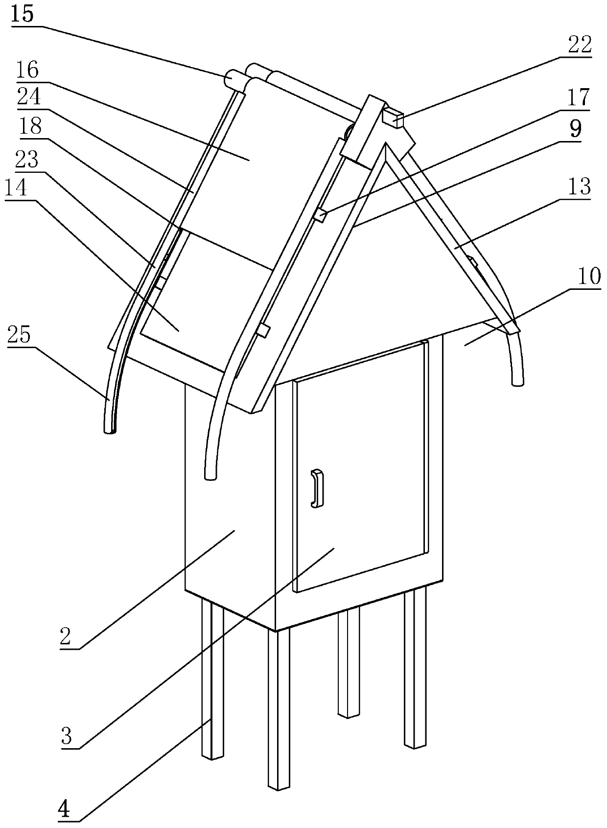
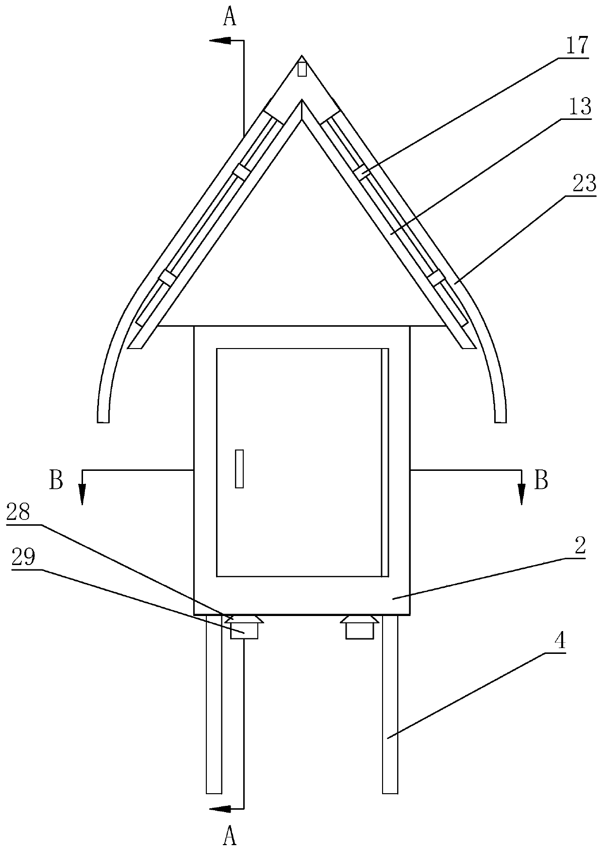
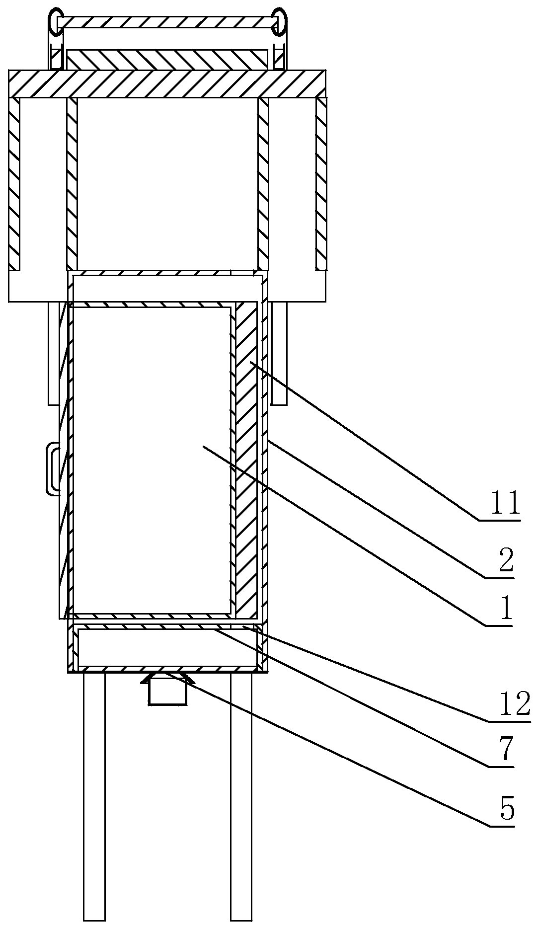
[0026] The present invention is an outdoor power box with self-protection function. The main structure includes an inner box 1 and an outer box 2. The inner box 1 is used to place electrical components in the existing power box. The outer box body 2 mainly has the functions of auxiliary heat dissipation and rainproof. One side of the inner box body 1 is provided with a box door 3. Preferably, the box door 3 is hinged to one side of the inner box...


PUM


Abstract

The invention discloses an outdoor power box with a self-protection function, and mainly relates to the field of power devices. The outdoor power box comprises an inner box body and an outer box body.One side of the inner box body is provided with a box door. The inner box body is sleeved by the outer box body. A support rod is arranged at the bottom of the outer box body. The bottom of the outerbox body is provided with an air inlet. Heat dissipation holes are arranged in the bottom and top of the inner box body and the top of the outer box body. A heat dissipation box is arranged in the outer box body. The heat dissipation box is located below the inner box body. Heat dissipation holes are arranged in the top and bottom of the heat dissipation box. A heat dissipation fan is arranged inthe heat dissipation box. An umbrella cover is arranged at the top of the outer box body. A heat dissipation channel is formed between the umbrella cover and the top of the outer box body. The bottomof the umbrella cover is lower than the top of the outer box body. The outdoor power box provided by the invention can ensure the heat dissipation demand of the power box, has a better rainproof effect, and can ensure normal operation of the power box.

Description

technical field [0001] The invention relates to the field of electric devices, in particular to an outdoor electric box with self-protection function. Background technique [0002] With the diversification of power consumption functions, the number and location of outdoor power boxes are gradually increasing. In order to facilitate the power demand near the road, a certain number of power boxes are usually set up near the green lawns beside the road. The power boxes serve as power The connected hub, the continuous work of its internal components will generate a lot of heat, so its heat dissipation is an aspect that needs to be considered. Therefore, cooling holes are usually set on the power box, but the outdoor power box will often encounter rain and snow. The baptism of rainwater can easily enter the power box from the cooling holes, affecting the normal work of internal components. Therefore, the problems of heat dissipation and rainproof of the outdoor power box are ofte...

Claims


Application Information

Patent Timeline
Patent Type & Authority Applications(China)
IPC IPC(8): H02B1/56H02B1/28H02B1/46
CPCH02B1/28H02B1/46H02B1/565
Inventor 李琦庄力行赵书民梁璐范子元祝永刚
Owner JINAN LICHENG POWER SUPPLY CO OF STATE GRID SHANDONG ELECTRIC POWER CO
Why Eureka
Try Eureka