
An automatic surface transfer coating drying equipment

A drying equipment and coating technology, which is applied in the direction of the device for coating liquid on the surface, the coating, the spraying device, etc., can solve the problems that the workpiece cannot be turned over automatically, the drying efficiency is low, and the drying is uniform, so as to facilitate automatic turning and improve Drying efficiency, easy access effect

Active Publication Date: 2021-06-29
平庆义
View PDF11 Cites 0 Cited by
  • Summary
  • Abstract
  • Description
  • Claims
  • Application Information

AI Technical Summary

Problems solved by technology

[0004] The purpose of the present invention is to solve the shortcomings in the prior art that the workpiece cannot be turned over automatically, manual turning is inconvenient for spraying, it is difficult to achieve uniform drying in the drying box, and it is not possible to blow air from multiple angles during drying, and the drying efficiency is low. A kind of automatic transfer surface coating drying equipment

Method used

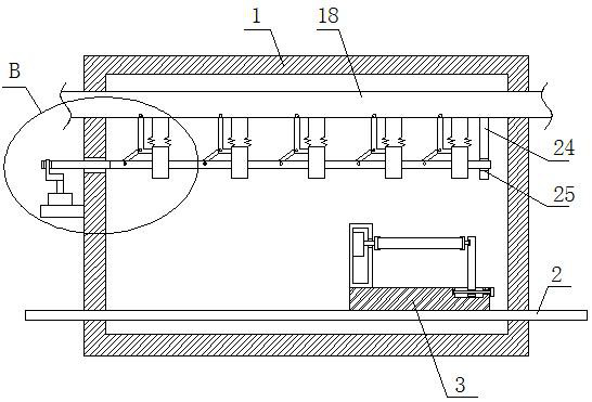

Image

  • An automatic surface transfer coating drying equipment
  • An automatic surface transfer coating drying equipment
  • An automatic surface transfer coating drying equipment

Examples


Embodiment 1

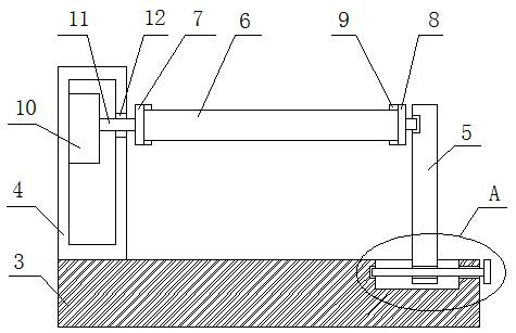
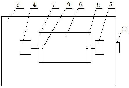
[0028] refer to Figure 1-5 , a kind of automatic surface coating drying equipment, including a drying box 1, a slide rail 2 is arranged in the drying box 1, a slide bar 3 is installed on the slide rail 2, a turning mechanism is provided on the top side of the slide bar 3, and the drying box 1 There is a blowing mechanism inside, and the turning mechanism includes a protective box 4 fixedly installed on the top side of the slide bar 3. One side of the protective box 4 is provided with an adjusting plate 5 that is movably installed on the top side of the slide bar 3. The adjusting plate 5 and the protective box The side close to each other of the box 4 is respectively rotated with a left clamping plate 7 and a right clamping plate 8, a workpiece body 6 is placed between the left clamping plate 7 and the right clamping plate 8, and the sides of the left clamping plate 7 and the right clamping plate 8 are respectively connected to the workpiece body. The two sides of 6 are in con...

Embodiment 2

[0039] refer to Figure 1-5 , a kind of automatic surface coating drying equipment, including a drying box 1, a slide rail 2 is arranged in the drying box 1, a slide bar 3 is installed on the slide rail 2, a turning mechanism is provided on the top side of the slide bar 3, and the drying box 1 There is a blowing mechanism inside, and the turning mechanism includes a protective box 4 fixedly installed on the top side of the slide bar 3 by welding. One side of the protective box 4 is provided with an adjusting plate 5 that is movably installed on the top side of the slide bar 3. The adjusting plate 5 and the side close to each other of the protective box 4 are respectively rotated with left clamping plate 7 and right clamping plate 8, and the workpiece body 6 is placed between the left clamping plate 7 and the right clamping plate 8, and the sides where the left clamping plate 7 and the right clamping plate 8 are close to each other are respectively In contact with both sides of...


PUM


Abstract

The invention belongs to the technical field of drying equipment, in particular to an automatic surface-turning coating drying equipment, aiming at the existing workpieces that cannot be turned over automatically, it is inconvenient to manually turn over and spray, it is difficult to achieve uniform drying in a drying box, and it cannot be dried more Due to the shortcomings of blowing at an angle and low drying efficiency, the following scheme is proposed, which includes a drying box, a slide rail is provided in the drying box, a slide bar is installed on the slide rail, and a turning mechanism is provided on the top side of the slide bar. A blowing mechanism is provided, and the turning mechanism includes a protective box fixedly installed on the top side of the slide bar. One side of the protective box is provided with an adjusting plate movably installed on the top side of the slide bar. The automatic surface-turning coating drying equipment of the present invention, Not only is it easy to turn over automatically when spraying, but it can also cooperate with the air supply mechanism to make the workpiece body dry faster and more evenly during drying. The workpiece body is easy to access. .

Description

technical field [0001] The invention relates to the technical field of drying equipment, in particular to an automatic surface-turning coating drying equipment. Background technique [0002] Automatic coating drying equipment, the power transmission mechanism drives the conveyor belt to transport the workpiece to be sprayed, and then passes through the feeding conveyor area, dust removal room, infrared preheating room, automatic coating room, infrared drying room, cooling workpiece area, and then to the The production line path in the unloading and conveying area to complete the spraying has already existed, but it is extremely troublesome to turn over the workpiece to be sprayed by hand in the automatic coating room, and it is easy to touch the wet paint on the workpiece and affect the coating quality . [0003] The patent with the publication number of CN107812681A discloses an automatic surface-turning coating drying equipment, which includes a drying box. Two slide rail...

Claims


Application Information

Patent Timeline
Patent Type & Authority Patents(China)
IPC IPC(8): B05B13/02B05D3/04
CPCB05B13/0228B05D3/0413
Inventor 平庆义
Owner 平庆义
Learn More