Throwing device applied to water rescue unmanned aerial vehicle system

A technology for unmanned aerial vehicles and rescue objects, which is applied to equipment for loading and unloading goods, launch devices, life rafts, etc., can solve the problems of overturning, shaking and errors of rescue objects, and achieve the effect of ensuring flight and convenient suspension.

Pending Publication Date: 2019-12-17
CHENGDU TIANFU NEW DISTRICT KUANG CHI FUTURE TECH INST
View PDF0 Cites 3 Cited by
  • Summary
  • Abstract
  • Description
  • Claims
  • Application Information

AI Technical Summary

Problems solved by technology

When multiple driving devices simultaneously drive the suspension parts to release the rescue objects, errors will inevitably result. Multiple suspension parts release the rescue objects out of sync, which will cause the rescue objects to flip after being dropped, and will cause unbalanced forces on the drone, resulting in shaking , the shaking is likely to cause the drone to lose control and crash

Method used


Image

  • Throwing device applied to water rescue unmanned aerial vehicle system
  • Throwing device applied to water rescue unmanned aerial vehicle system
  • Throwing device applied to water rescue unmanned aerial vehicle system

Examples


Embodiment 1

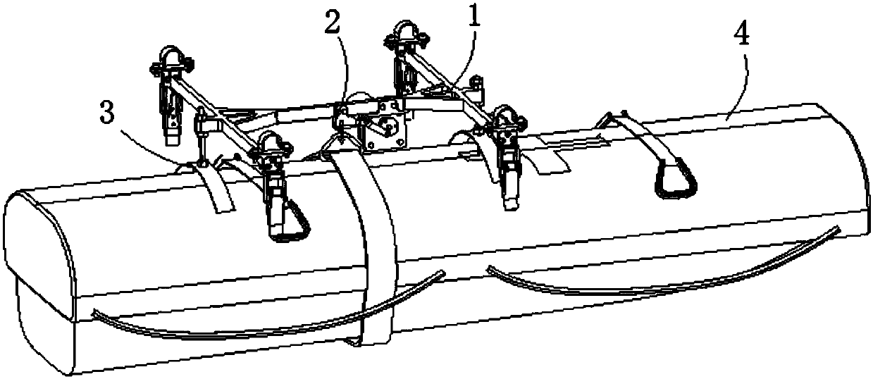
[0019] This embodiment provides a throwing device. The throwing device is used to be installed on an unmanned aerial vehicle to throw rescue objects, and is mainly used for water rescue. In this embodiment, the rescue objects thrown by the throwing device are described by taking the lifeboat as an example.

[0020] Such as figure 1 As shown, the throwing device of this embodiment mainly includes a bracket 1 , a suspension component 2 and a limit component 3 . The bracket 1 is used to be installed on the lower end of the drone, the suspension assembly 2 and the limit assembly 3 are respectively installed on the lower end of the support 1, the suspension assembly 2 is used to hang the lifeboat 4, and the limit assembly 3 is used to limit the lifeboat 4.

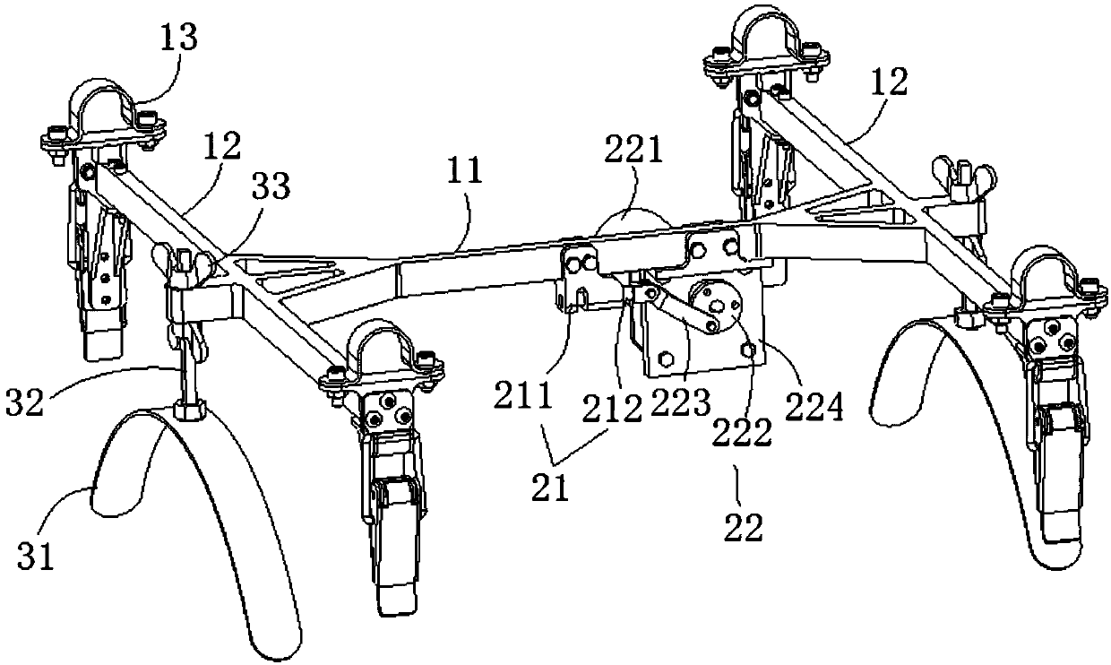
[0021] Specifically, such as figure 2 As shown, the support 1 includes a crossbeam 11 and a longitudinal beam 12. The longitudinal beam 12 has two parallel beams. A crossbeam 11 is connected to the middle of the two longitud...

Embodiment 2

[0030] This embodiment provides a throwing device. The difference between the throwing device of this embodiment and the above embodiment is that the structure of the bracket is different and the number and installation position of the limiting parts are different. The throwing device is mainly used for life buoys.

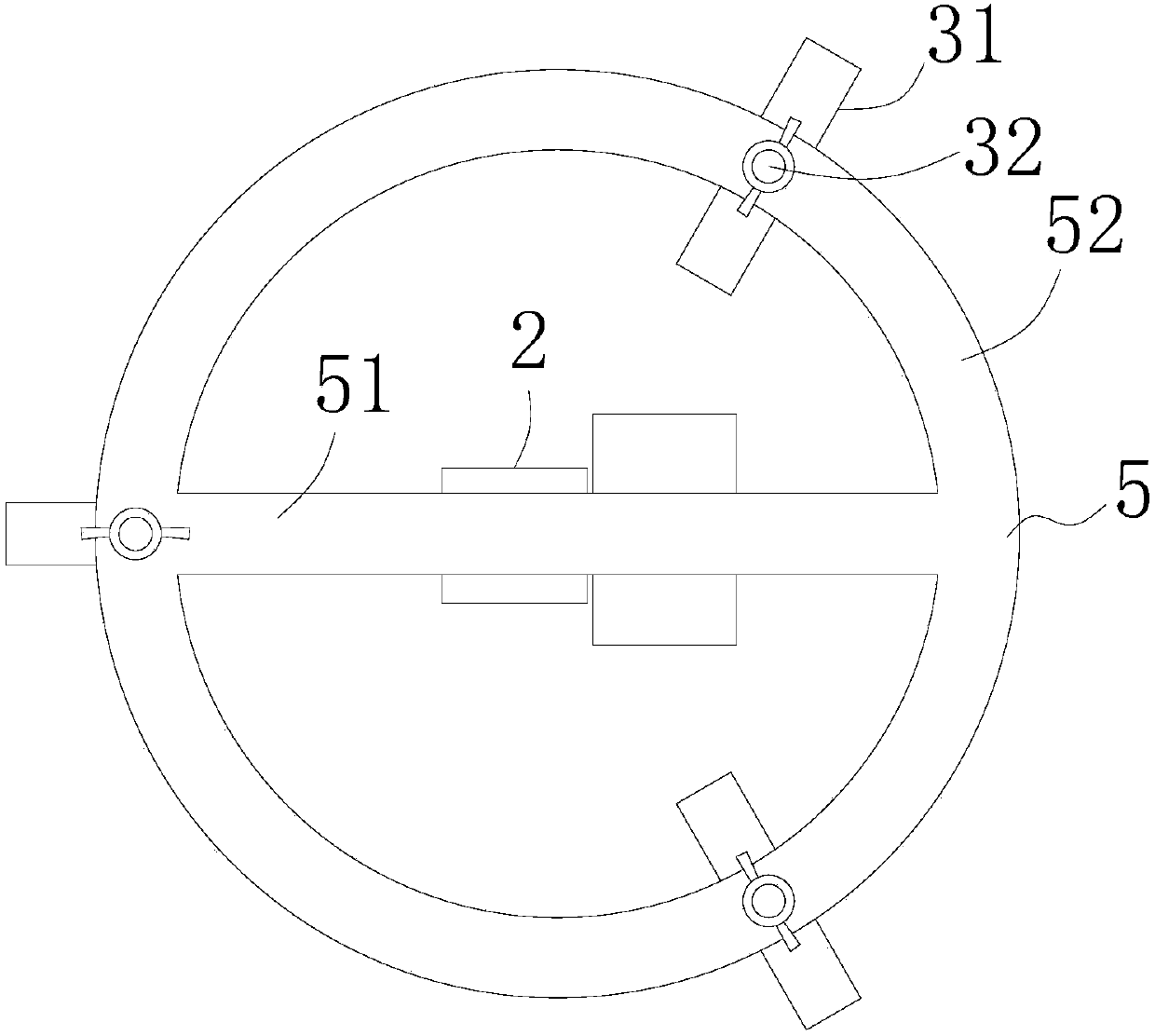
[0031] Such as image 3 As shown, in this embodiment, the bracket 5 includes a beam 51 and a ring beam 52 , the beam 51 is installed in the middle of the ring beam 52 , and the suspension assembly 2 is installed at the lower end of the beam 51 . There are three stoppers 31 , which are evenly distributed and installed on the lower end of the ring beam 52 , and the stoppers 31 are adjustable through the adjusting rod 32 .

[0032] In the throwing device of this embodiment, the suspension assembly 2 located in the middle is used to hang the lifebuoy, and the limiting parts 31 located around are used to limit the shaking of the lifebuoy. Also, only one driving part c...

Embodiment 3

[0034] This embodiment provides a throwing device. On the basis of the above two embodiments, a binding assembly is added. The binding assembly is used to bind the rescue object and hang the rescue object on the suspension assembly 2 . This embodiment is described by taking the addition of a binding component on the basis of Embodiment 1 as an example.

[0035] Such as Figure 4 As shown, the binding assembly 6 includes a safety belt 61, a triangular hanging ring 62 and a suspension ring 63, the safety belt 61 is used for binding on the lifeboat 4, the triangular hanging ring 62 is set on the safety belt 61, and the suspension ring 63 is connected to the triangle hanging On the ring 62, the upper end of the suspension ring 63 is used to be inserted into the pin buckle 211 for hanging and fixing.

[0036] In other embodiments, in order to bind the life buoy, there are multiple safety belts 61 , and the plurality of safety belts 61 are collected and connected to the triangle ha...


PUM


Abstract

The invention discloses a throwing device applied to a water rescue unmanned aerial vehicle system. The throwing device comprises a support, a suspension assembly and a limiting assembly; the suspension assembly comprises a suspension part and a driving part, wherein the suspension part is used for suspending rescue materials; the suspension part is arranged at the lower end of the middle of the support; the driving part is arranged on the support, is connected to the suspension part and is used for driving the suspension part to be opened and closed; the limiting assembly comprises at least two limiting parts used for limiting shaking of the rescue materials; and the limiting parts are arranged at the lower end of the edge of the support. According to the throwing device, the suspension assembly is arranged at the lower end of the middle of the support, the at least two limiting parts are arranged at the edge of the support, the rescue materials can be fixed through the suspension part located in the middle and then are limited through the limiting parts located at the edge so as to prevent the rescue materials from shaking, so that only one driving part needs to be arranged to drive the suspension part to be opened and closed so as to complete suspension and throwing of the rescue materials, one suspension point and two limiting points are arranged, so that the rescue materials can fall stably in the throwing process, and therefore the flight of an unmanned aerial vehicle is guaranteed, and suspension of the rescue materials is also facilitated.

Description

technical field [0001] The application relates to water rescue equipment, in particular to a throwing device applied to a water rescue UAV system. Background technique [0002] With the development and application of UAVs, UAVs play an important role in water rescue. UAVs can transport rescue objects to designated rescue locations in time. In order to facilitate UAV loading and throwing rescue objects, in A throwing device is installed on the frame at the lower end of the UAV, and the throwing device has the functions of quick clamping and throwing rescue objects. [0003] In the prior art, the throwing device all adopts a plurality of suspension parts to fix the rescue object, and each suspension part is driven by a driving device (steering gear) respectively to realize throwing. When multiple driving devices simultaneously drive the suspension parts to release the rescue objects, errors will inevitably result. Multiple suspension parts release the rescue objects out of sy...

Claims


Application Information

Patent Timeline
Patent Type & Authority Applications(China)
IPC IPC(8): B64D1/02B64D9/00B64C39/02B63C9/01
CPCB63C9/01B64C39/02B64D1/02B64D9/00
Inventor 刘若鹏栾琳何圳涛韩凛
Owner CHENGDU TIANFU NEW DISTRICT KUANG CHI FUTURE TECH INST
Why Eureka
Try Eureka