
Portable cloth cutting and punching device

A hole punch, portable technology, applied in the field of clothing manufacturing, can solve the problems of clothes debris stuck, reduce use efficiency, cannot be removed, etc., achieve the effect of various hole patterns, reduce design errors, and keep clean

Inactive Publication Date: 2019-12-20
扬州尚衣汇时装设计有限公司
View PDF0 Cites 1 Cited by
  • Summary
  • Abstract
  • Description
  • Claims
  • Application Information

AI Technical Summary

Problems solved by technology

[0002] In the garment manufacturing industry, fabrics need to go through multiple processes before they can be sold on the market. The use of fabrics includes spreading, cutting and processing of fabrics, especially square fabrics, that is, fabrics that are cut into square strips. Nowadays, automatic processing is widely used. In the production process of clothing, it is often necessary to grind or grind small holes on the clothes. This process requires the use of a puncher. The puncher is a very There are many textile products that require punching, and the development of punching devices in the textile industry is also very rapid; for small clothing designers and processors, they do not need to use many large and super large clothing manufacturers in China. Enterprises have advanced automatic punchers, but need to design a small portable puncher, and the existing puncher can only punch a small hole of a hole type, and the punch is fixed and not suitable for replacement. It is not suitable for design and processing personnel who often need to design and process different hole types; and the clothes debris generated during the grinding process will be stuck in the equipment and cannot be removed. It must be cleaned regularly afterwards, which reduces the use efficiency

Method used


Image

  • Portable cloth cutting and punching device
  • Portable cloth cutting and punching device
  • Portable cloth cutting and punching device

Examples


Embodiment Construction

[0014] Below in conjunction with accompanying drawing and specific embodiment, further illustrate the present invention, should be understood that these embodiments are only for illustrating the present invention and are not intended to limit the scope of the present invention, after having read the present invention, those skilled in the art will understand various aspects of the present invention Modifications in equivalent forms all fall within the scope defined by the appended claims of this application.

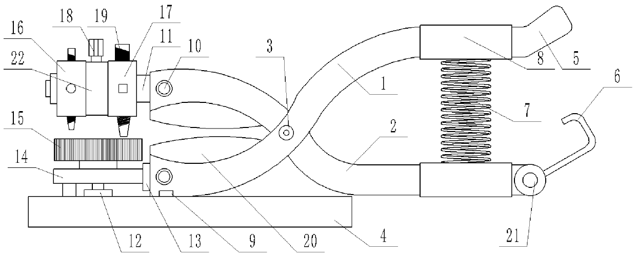
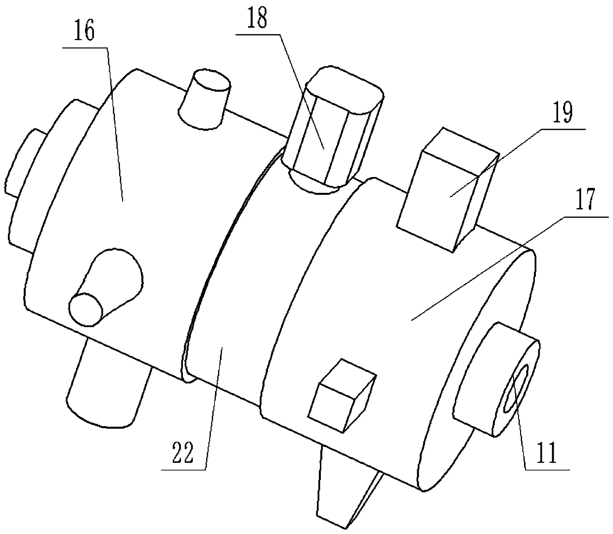
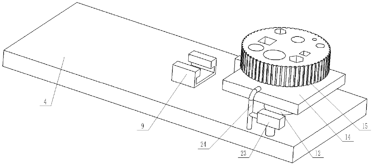
[0015] like figure 1 As shown, the self-cleaning cloth puncher with adjustable pass type includes a fixed handle 1, a rotating handle 2, a connecting piece 3, a punching structure and a punching seat structure, and the middle part of the fixed handle 1 and the middle part of the rotating handle 2 pass through The connecting piece 3 is connected to form a scissors shape. The fixed handle 1 and the rotating handle 2 are provided with a cutting edge 20 near the front end. T...


PUM


Abstract

The invention discloses a portable cloth cutting and punching device, and belongs to the field of apparel manufacturing. The portable cloth cutting and punching device comprises a cutting structure, apunching structure and a fixing structure; the punching structure and the fixing structure are detachably mounted on the cutting structure. A main body of the punching device is of a cutting knife structure, the various positions of the cutting knife are improved, and different structures are detachably mounted on the various positions of the cutting knife, so that the effects that cloth is cut,holes in different shapes are punched, and cloth chips are cleaned are reached, and the portable cloth cutting and punching device is simple in structure, is multifunctional and portable, and is verypractical for small apparel designers and processors.

Description

technical field [0001] The invention belongs to the field of clothing manufacturing, and specifically refers to a portable cloth cutting and punching device. Background technique [0002] In the garment manufacturing industry, fabrics need to go through multiple processes before they can be sold on the market. The use of fabrics includes spreading, cutting and processing of fabrics, especially square fabrics, that is, fabrics that are cut into square strips. The processing is developed from the initial pure manual Nowadays, automatic processing is widely used. In the production process of clothing, it is often necessary to grind or grind small holes on the clothes. This process requires the use of a puncher. The puncher is a very There are many textile products that require punching, and the development of punching devices in the textile industry is also very rapid; for small clothing designers and processors, they do not need to use many large and super large clothing manufac...

Claims


Application Information

Patent Timeline
Patent Type & Authority Applications(China)
IPC IPC(8): B26F1/02B26D1/30B26D7/18B26D5/10
CPCB26D1/305B26D5/10B26D7/1854B26F1/02B26F2001/365
Inventor 鲍怀敏侯菊华万才芳徐丽张玉良
Owner 扬州尚衣汇时装设计有限公司
Learn More