
Temporary road rapid threading pipeline and threading method
A technology for temporary roads and threading pipes, applied in the directions of roads, roads, pavement details, etc., can solve problems such as line confusion, limiting the number of threading, and affecting the construction progress.
- Summary
- Abstract
- Description
- Claims
- Application Information
AI Technical Summary
Problems solved by technology
Method used
Image

Examples
Embodiment Construction
[0026] Below in conjunction with embodiment and accompanying drawing, the present invention will be further described:
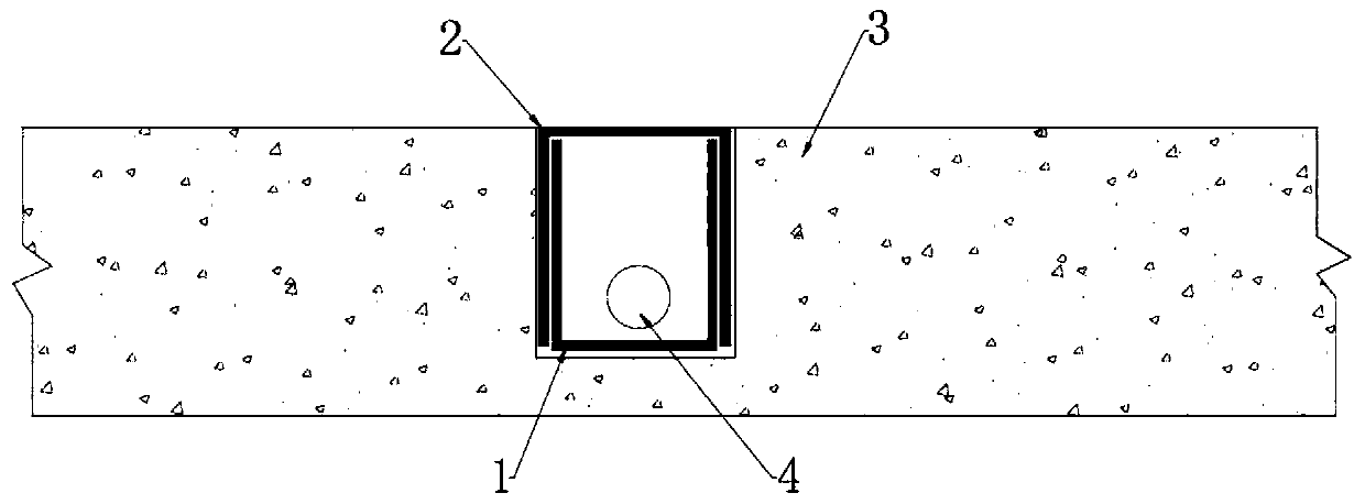
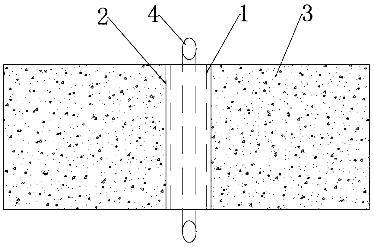
[0027] In one embodiment of the present invention, as figure 1 and figure 2 As shown, the temporary road rapid threading pipeline includes: first channel steel 1, second channel steel 2, concrete pavement 3, and line 4. The closed end of the first channel steel 1 is embedded in the concrete pavement 3, the open end of the first channel steel 1 is arranged inside the open end of the second channel steel 2, and the closed end of the second channel steel 2 is flush with the surface of the concrete pavement 3 Flat, the line 4 is set in the cavity surrounded by the first channel steel 1 and the second channel steel 2 .
[0028] Preferably,
[0029] The second channel steel 2 is provided with a mechanism for making the second channel steel 2 move up and down relative to the first channel steel 1 .
[0030] More preferably, the inner bottoms of the first chann...
PUM
 Abstract
Description
Claims
Application Information