Control method of electronic lock, key and lock

A control method and key technology, which is applied to the control of electronic locks, keys and locks, can solve the problems of low energy conversion efficiency, complex structure of electronic locks, and inability to switch between power supply mode and communication mode of electronic locks.

Active Publication Date: 2019-12-20
ZHUHAI UNITECH POWER TECH CO LTD
View PDF5 Cites 6 Cited by
  • Summary
  • Abstract
  • Description
  • Claims
  • Application Information

AI Technical Summary

Problems solved by technology

[0005] Embodiments of the present invention provide a control method, a key and a lock for an electronic lock, so as to at least solve the technical problems in the related art that the power supply mode and the communication mode of the electronic lock cannot be switched, resulting in a complex structure of the electronic lock and low energy conversion efficiency

Method used


Image

  • Control method of electronic lock, key and lock
  • Control method of electronic lock, key and lock
  • Control method of electronic lock, key and lock

Examples


Embodiment 1

[0033] According to an embodiment of the present invention, an embodiment of a method for controlling an electronic lock is provided. It should be noted that the steps shown in the flow chart of the accompanying drawings can be executed in a computer system such as a set of computer-executable instructions, and , although a logical order is shown in the flowcharts, in some cases the steps shown or described may be performed in an order different from that shown or described herein.

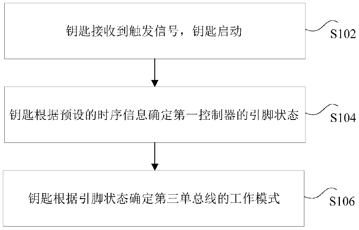
[0034] figure 1 It is a control method of an electronic lock according to an embodiment of the present invention, the electronic lock includes a key and a lock, the key includes a first controller, a first single bus, and the lock includes a second single bus, such as figure 1 As shown, the method includes the following steps:

[0035] Step S102, the key receives a trigger signal, and the key starts, wherein the trigger signal is generated when the first single bus and the second single bus are c...

Embodiment 2

[0092] According to an embodiment of the present invention, a key is provided, including: a first single bus connected to a first controller for generating a trigger signal, wherein the trigger signal is connected to the second single bus of the lock on the first single bus generated under the condition; the first controller is used to determine the pin state of the first controller according to the preset timing information after receiving the trigger signal, and determine the working mode of the third single bus according to the pin state, wherein , the third single bus is a circuit formed by connecting the first single bus and the second single bus, and the working mode includes a power supply mode and a communication mode.

[0093] Optionally, the first controller includes a communication pin, and the key determines the working mode of the third single bus according to the state of the pin, including: if the communication pin outputs the first level, the third single bus is...

Embodiment 3

[0101] According to an embodiment of the present invention, a lock is provided, including:

[0102] The second single bus, connected to the second controller, is used to generate a trigger signal to start the key, wherein the trigger signal is generated when the first single bus of the key is connected to the second single bus;

[0103] The second controller is used to control the third single bus to work in a corresponding working mode according to the instruction of the key, wherein the instruction is determined based on the timing information preset by the key, and the third single bus is the connection between the first single bus and the second single bus. The working mode includes power supply mode and communication mode.

[0104] Optionally, the lock further includes a drive circuit, a motor and a mechanical lock. If the mechanical lock matches the teeth of the key and the key passes the electronic verification of the lock, the lock drives the motor to a preset position...


PUM


Abstract

The invention discloses a control method of an electronic lock, a key and a lock. The electronic lock comprises a key and a lock, wherein the key comprises a first controller and a first single bus; the lock comprises a second single bus. The control method of the electronic lock comprises the following steps: receiving a trigger signal through the key, and starting the key, wherein the trigger signal is generated under the condition that the first single bus and the second single bus are connected; determining the pin state of the first controller through the key according to preset time sequence information; and determining the working mode of a third single bus through the key according to the pin state, wherein the third single bus is a line formed by connecting the first single bus and the second single bus; and the working mode includes a power supply mode and a communication mode. The method solves the technical problems of complex structure and low energy efficiency conversionefficiency of an electronic lock caused by the fact that the power supply mode and the communication mode of the electronic lock cannot be switched in the related technology.

Description

technical field [0001] The invention relates to the field of electronic locks, in particular to a control method, a key and a lock for an electronic lock. Background technique [0002] The two-wire single bus has the functions of both communication and power supply, and has the advantages of long communication distance, support for multi-node equipment, and support for event interruption. being widely used. However, in some specific fields, such as the field of electronic locks, due to the complex structure of the modulation and demodulation circuit and low energy efficiency conversion efficiency, the binary single bus is difficult to meet the requirements of low cost, high energy efficiency conversion efficiency and fast response speed. [0003] In order to solve the above problems, the prior art can realize the dual functions of communication and power supply and take-off by setting circuits inside the key, electronic lock and authorizer and connecting them through single...

Claims


Application Information

Patent Timeline
Patent Type & Authority Applications(China)
IPC IPC(8): E05B47/00E05B51/00E05B19/00E05B15/00
CPCE05B47/0012E05B19/00E05B47/00E05B51/00E05B15/00E05B2047/0057
Inventor 李保福杨绍华阳仲伯陈华
Owner ZHUHAI UNITECH POWER TECH CO LTD
Why Eureka
Try Eureka