
Electromagnetic clamp type anti-falling rod dismounting device

A clamp-type, anti-fall technology, applied in drill pipe, drilling equipment, earth-moving drilling, etc., can solve the problems of damage to construction equipment and other facilities, threat to personnel safety, high labor intensity, etc., to reduce auxiliary work time, production Simple materials and the effect of reducing labor intensity

Pending Publication Date: 2022-04-12
中国水利水电第七工程局成都水电建设工程有限公司
View PDF0 Cites 0 Cited by
  • Summary
  • Abstract
  • Description
  • Claims
  • Application Information

AI Technical Summary

Problems solved by technology

We often use down-the-hole drilling and geological drilling equipment, which may easily cause safety accidents when adding and unloading drill pipes
In the anchoring project, when constructing the upward hole, when the drill pipe is lengthened or dismantled, there is no suitable support for the drill pipe in the hole, and the construction personnel need to add auxiliary supports on site, install pad forks, etc. to solve the problem, which is labor-intensive and unsafe
Deep hole curtain construction also uses pad forks to load and unload drill pipes, which also brings unsafe risks and is time-consuming and laborious
Moreover, with the increase in the weight of the drill pipe and the limitation of the environment, it not only poses a threat to the safety of personnel, but once the drill pipe in the hole slips, the construction equipment and other facilities will be damaged.
Therefore, it is very dangerous to use pad forks

Method used


Image

  • Electromagnetic clamp type anti-falling rod dismounting device
  • Electromagnetic clamp type anti-falling rod dismounting device
  • Electromagnetic clamp type anti-falling rod dismounting device

Examples


Embodiment Construction

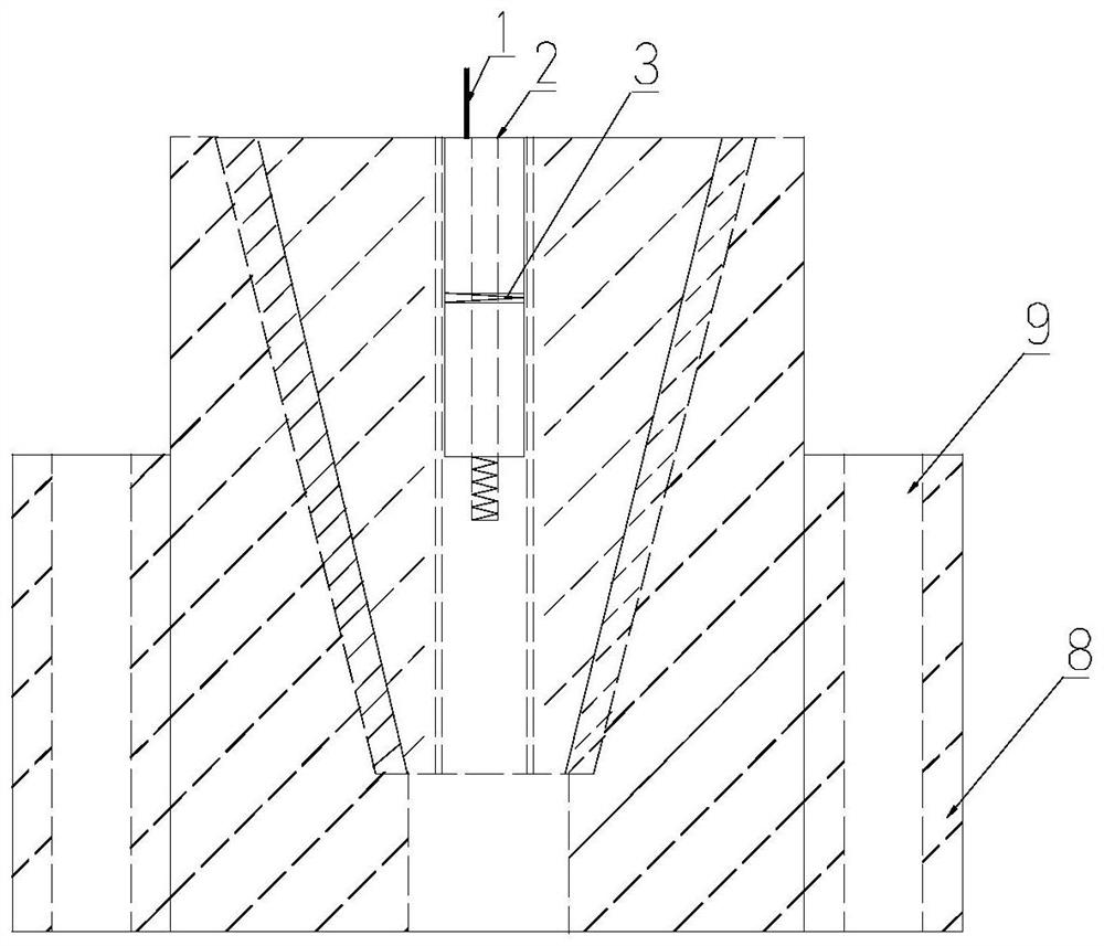
[0026] The present invention will be further described below in conjunction with specific embodiments, see Figure 1 to Figure 7 , the present invention provides a kind of electromagnetic clamp type anti-drop rod device, it comprises upper and lower two parts, and upper part is male tool or male tool (hereinafter collectively referred to as male tool), and lower part is female tool or female tool (hereinafter collectively referred to as female tool) ). The male and female are connected coaxially.

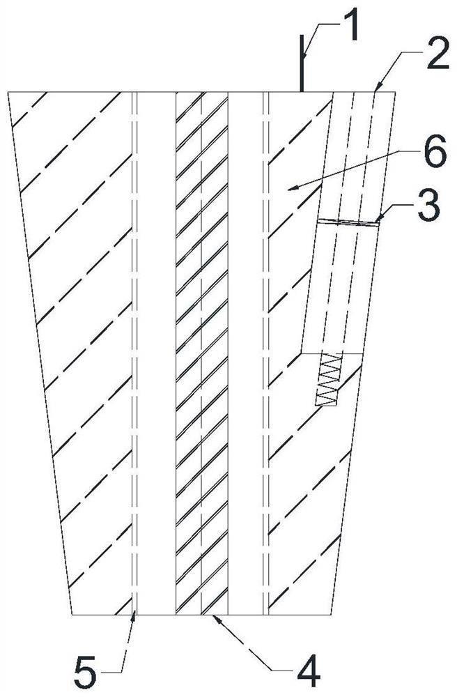
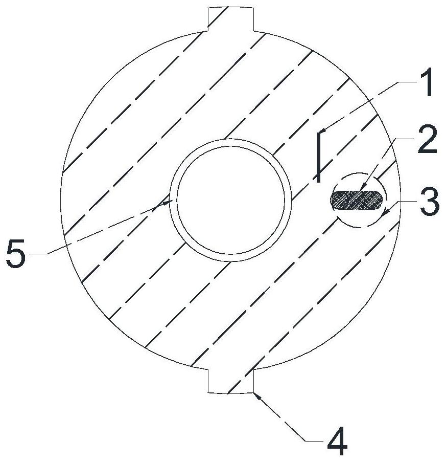
[0027] The male tool is a hollow conical column structure, which is composed of two electromagnets 6 on the left and right. The two electromagnets 6 on the left and right are the clamps. The iron 6 is terminated with an electromagnet outlet 1, and two electromagnets 6 are energized to hold the drill pipe tightly, and the power is cut off to loosen naturally. The hollow part inside the male tool is cylindrical, which is the guide hole of the male tool. The hollow part is the space ...


PUM


Abstract

An electromagnetic clamp type anti-falling rod dismounting device comprises a male tool on the upper portion and a female tool on the lower portion. The male tool is composed of a left electromagnet and a right electromagnet and is of a hollow conical column structure, the left electromagnet and the right electromagnet are connected into a whole through a through pin and a spring, the hollow part inside the male tool is cylindrical, a rubber insulating material is arranged on the inner wall of the male tool, and a group of first tenons are symmetrically and fixedly arranged outside the male tool; the female tool is of a hollow cylinder structure, the upper portion of the hollow part is in an inverted cone column shape, the lower portion of the hollow part is in a cylinder shape, a set of second tenons are symmetrically and fixedly arranged outside the cylinder, stabilizing bolt holes are formed in the second tenons, and four grooves matched with the first tenons on the two sides of the male tool are symmetrically formed in the hollow inner wall of the inverted cone column shape. The female tool is installed on a machine head of the drilling machine through a stabilizing bolt. During use, after the male tool and the female tool are tightly meshed, the drill rod can be prevented from falling, the purpose of dismounting can be achieved when a drilling machine rotates reversely, safety risks are reduced, labor intensity is lowered, and construction efficiency is improved.

Description

Technical field: [0001] The invention relates to the technical field of anchoring construction and grouting construction engineering, in particular to the technical field of top arch anchorage upward hole construction and deep hole curtain construction. Specifically, it is an electromagnetic clamp type anti-fall rod device. Background technique: [0002] In engineering anchoring with complex geological conditions, large-tonnage prestressed anchor cables and foundation grouting have been widely popularized and applied in the reinforcement of complex geology and extra-large caverns. However, the selection of high-quality construction equipment is the key to ensuring the quality and safety of construction. The underground powerhouse of a hydropower station is generally a typical "three-cavity structure", which is the main powerhouse, the main transformer tunnel, and the busway. In the entire underground powerhouse, the amount of anchoring and grouting construction is huge, and ...

Claims


Application Information

Patent Timeline
Patent Type & Authority Applications(China)
IPC IPC(8): E21B19/18
Inventor 廖军杨绍寅肖铧贺子英蒙万谦邵方敬唐应鹏刘代贤刘均锋刘鹏程李翔王礼汤华国甘全坤廖天明
Owner 中国水利水电第七工程局成都水电建设工程有限公司
Learn More