
Oil well monitoring device and method

A monitoring equipment and oil well technology, which is applied in the field of oil exploration monitoring, can solve the problems of large measurement error, large error of oil well liquid production, large error of liquid production, etc., to simplify the mathematical calculation model, save manpower and material resources, and achieve high measurement accuracy high effect

Active Publication Date: 2019-12-20
SHANDONG TIANGONG PETROLEUM EQUIP
View PDF5 Cites 4 Cited by
  • Summary
  • Abstract
  • Description
  • Claims
  • Application Information

AI Technical Summary

Problems solved by technology

However, in the above-mentioned various metering methods, the liquid volume is basically measured, and the gas content cannot be measured at the wellhead.
[0004]According to the fluid discharge characteristics of the oil well, during the upstroke process, the liquid flows out one by one, and during the downstroke process, the liquid basically does not come out, thus causing the aforementioned vortex Street flowmeters, ultrasonic flowmeters, turbine flowmeters, metal float flowmeters and other devices have large measurement errors, which cannot meet the needs of oil field production
However, when the oil well weighing and measuring device is used for measurement, due to its intermittent measurement, such as measuring once every three days, the calculated oil well fluid production has a large error, and when the oil well has an abnormal situation, the problem cannot be found in time
When using oil well dynamometer diagram to calculate oil well liquid production, although the problem of large liquid production error has been improved, it is still impossible to judge abnormal conditions such as tubing leakage, and this measurement method cannot be used for heavy oil wells and special wells

Method used


Image

  • Oil well monitoring device and method
  • Oil well monitoring device and method
  • Oil well monitoring device and method

Examples


Embodiment Construction

[0045]In order to make the purpose, technical solutions and advantages of the embodiments of the present invention clearer, the technical solutions in the embodiments of the present invention will be clearly and completely described below in conjunction with the drawings in the embodiments of the present invention. Obviously, the described embodiments It is a part of embodiments of the present invention, but not all embodiments. Based on the embodiments of the present invention, all other embodiments obtained by persons of ordinary skill in the art without making creative efforts belong to the protection scope of the present invention.

[0046] In the following detailed description, reference is made to the accompanying drawings which are included in the specification and which illustrate specific embodiments of the application and which are included in this application. In the drawings, like reference numerals describe substantially similar components in different views. Var...


PUM


Abstract

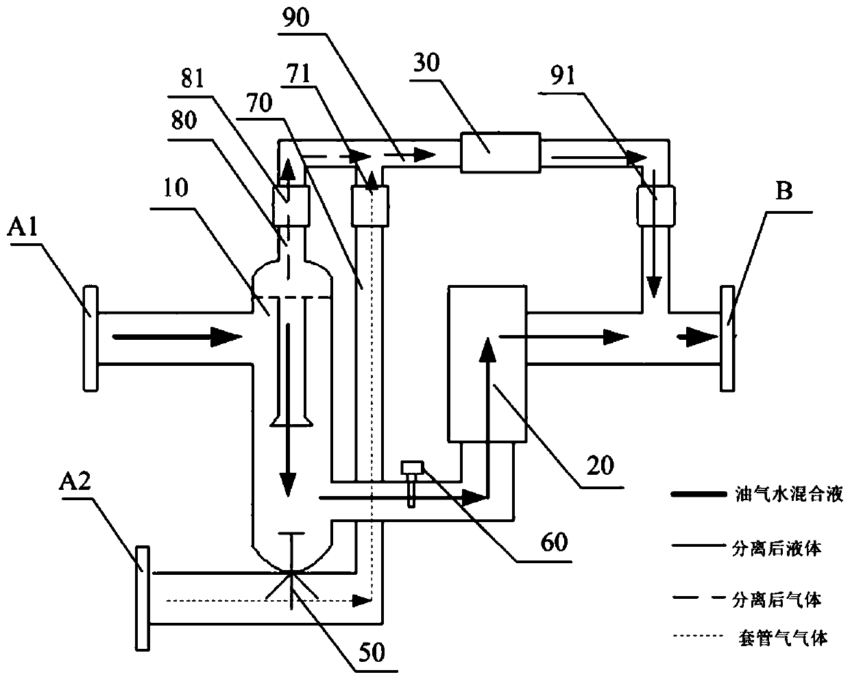
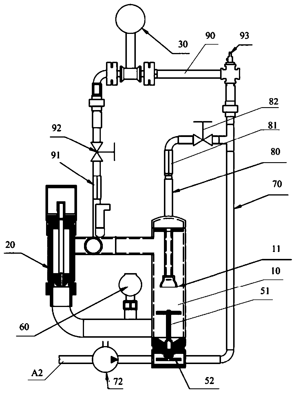
The invention relates to an oil well monitoring device and method. The oil well monitoring device comprises a mixed liquid inlet of oil, gas, and water, a mixed liquid outlet of the oil, the gas, andthe water, a gas-liquid separator, a liquid monitoring component, a gas monitoring component, and a data processing device, wherein the mixed liquid inlet and the mixed liquid outlet are connected toan oil well wellhead ground pipeline; an entering opening of the gas-liquid separator is connected with the mixed liquid inlet, and the gas-liquid separator is configured to perform gas-liquid phase separation on a mixed liquid; the liquid monitoring component is connected between a liquid outlet of the gas-liquid separator and the mixed liquid outlet, and is configured to collect liquid monitoring data; the gas monitoring component is connected between a gas outlet of the gas-liquid separator and the mixed liquid outlet, and is configured to collect gas monitoring data; and the data processing device is configured to calculate a liquid production amount of an oil well according to the liquid monitoring data and calculate gas production amount of the oil well according to the gas monitoring data. According to the oil well monitoring device, the liquid / gas production amount of the oil well can be metered in real time, and the manual participation is not needed; and the oil well abnormality can be found in time, and an alarm is given in time when a safety problem appears.

Description

technical field [0001] The invention relates to the technical field of oil production monitoring, in particular to an oil well monitoring device and method. Background technique [0002] In the process of oil extraction, ground oil production equipment, such as pumping units, draws the mixture of oil, gas and water from the formation, and transports it through ground pipelines, such as transporting it to an oil storage tank for temporary storage. Among them, in order to transport safely, it is necessary to detect the pressure and temperature of the mixed liquid output from the wellhead; in order to determine the production of the oil well, it is necessary to install a metering device to measure the production of the oil well. [0003] In the prior art, when measuring the output, the liquid production of the oil well is usually measured, such as installing a vortex flowmeter, an ultrasonic flowmeter, a metal float flowmeter and other devices in the pipeline; or using an oil w...

Claims


Application Information

Patent Timeline
Patent Type & Authority Applications(China)
IPC IPC(8): E21B47/00E21B47/06E21B47/07E21B43/34
CPCE21B47/00E21B47/06E21B43/34E21B47/10G01F15/08E21B21/002E21B49/005
Inventor 田海峰李新华王建林
Owner SHANDONG TIANGONG PETROLEUM EQUIP
Learn More