Engine exhaust waste heat recovery system

A waste heat recovery and engine technology, which is applied in the direction of engine components, combustion engines, engine cooling, etc., can solve the problems of increasing costs and unfavorable weight reduction of automobiles

Inactive Publication Date: 2019-12-20
CHONGQING CHANGAN AUTOMOBILE CO LTD
View PDF8 Cites 1 Cited by
  • Summary
  • Abstract
  • Description
  • Claims
  • Application Information

AI Technical Summary

Problems solved by technology

But installing a heat shield will not only increase

Method used


Image

  • Engine exhaust waste heat recovery system

Examples


Embodiment Construction

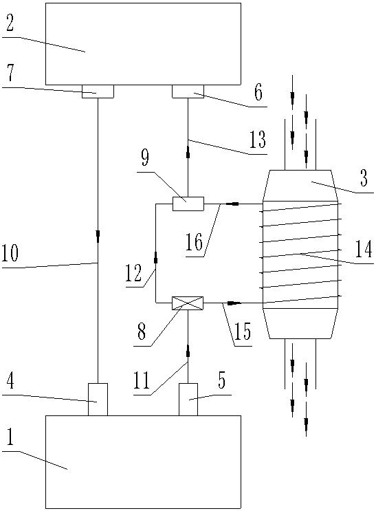
[0017] The present invention will be further described below in conjunction with accompanying drawing.

[0018] Such as figure 1 The shown engine exhaust waste heat recovery system includes an engine 1, a heater 2, an automobile exhaust catalyst 3, a thermostat 8, a tee joint 9 and a heat exchange element 14; the engine 1 is provided with an engine water inlet 4 and the engine water outlet 5; the heater 2 is provided with a heater water inlet 6 and a heater outlet 7; the thermostat 8 is provided with a thermostat water inlet, a first thermostat outlet and a second thermostat Water outlet; the heat exchange element 14 is arranged on the periphery of the automobile exhaust catalytic converter 3, the heat exchange element 14 is provided with a heat exchange element water inlet and a heat exchange element water outlet, and the heat exchange element 14 is provided with a water inlet connected to the heat exchange element and The liquid flow path of the water outlet of the heat exc...


PUM


Abstract

The invention relates to an engine exhaust waste heat recovery system. The system comprises an engine, a fan heater, an automobile exhaust catalyst, a thermostat, a three-way joint and a heat exchangepart; an engine water inlet and an engine water outlet are formed in the engine; the heat exchange part is arranged at the periphery of the automobile exhaust catalyst, and the heat exchange part isprovided with a heat exchange part water inlet and a heat exchange part water outlet; the engine water outlet communicates with a thermostat water inlet through a pipeline, and a thermostat water outlet communicates with a heat exchange part water inlet through the pipeline; and the three joints of the three-way joint correspondingly communicate with the other thermostat water outlet, the heat exchange part water outlet and a fan heater water inlet through the pipeline, and a fan heater water outlet communicates with an engine water inlet through the pipeline. The system has the advantages that the water temperature of the engine can be rapidly improved, and the requirement of customers on rapid temperature rise of warm air of an air conditioner can be met; and meanwhile, a heat insulationstructure of the automobile exhaust catalyst is formed through the heat exchange part, so that the cost is reduced, and the lightweight of an automobile is facilitated.

Description

technical field [0001] The invention relates to an automobile engine assembly, in particular to an engine exhaust waste heat recovery system. Background technique [0002] With the popularity of automobile products, automobiles have been widely used in various regions of the world, whether in tropical or frigid regions. The temperature in frigid regions is generally low, even reaching minus 40-50 degrees Celsius. Frequent short-distance driving will make it difficult for the engine to reach the ideal operating temperature. Diluted and emulsified engine oil may occur, affecting the normal operation of the engine lubrication system. In severe cases, the engine may be scrapped due to poor lubrication. The high speed and slow speed make it impossible to quickly meet the customer's demand for air conditioning and heating. [0003] The three-way catalytic converter is the most important external purification device installed in the automobile exhaust system. It can convert some h...

Claims


Application Information

Patent Timeline
IPC IPC(8): F01N3/20B60H1/02F01N13/14F01P7/14F02G5/04
CPCB60H1/025F01N3/2046F01N13/14F01P7/14F02G5/04F02G2260/00Y02T10/12Y02A50/20
Inventor 曹刚赵勇郑素芳王开逍程伟刘涓邱波郭江
Owner CHONGQING CHANGAN AUTOMOBILE CO LTD
Why Eureka
Try Eureka