Blade boundary layer flow control system and wind power generating set including same

A flow control and boundary layer technology, applied in the direction of wind motor combination, wind engine, and wind engine consistent with the wind direction, can solve the problems of losing the meaning of power increase, energy loss, etc., to increase power generation, delay stall, Effect of suppressing blade boundary layer separation

Active Publication Date: 2021-04-16
SHANGHAI ELECTRIC WIND POWER GRP CO LTD
View PDF11 Cites 0 Cited by
  • Summary
  • Abstract
  • Description
  • Claims
  • Application Information

AI Technical Summary

Problems solved by technology

[0007] The technical problem to be solved by the present invention is to provide a blade boundary layer flow control system and its of wind turbines

Method used


Image

  • Blade boundary layer flow control system and wind power generating set including same
  • Blade boundary layer flow control system and wind power generating set including same
  • Blade boundary layer flow control system and wind power generating set including same

Examples


Embodiment 1

[0043] like Figure 1-Figure 7 As shown, this embodiment discloses a blade boundary layer flow control system, wherein the blade boundary layer flow control system includes a fan blade, a first guide section and a second guide section.

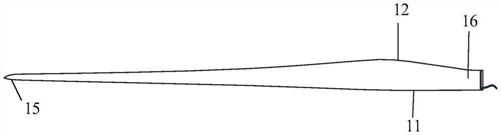
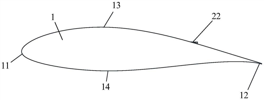
[0044] like figure 1 and image 3As shown, the blade boundary layer flow control system of this embodiment includes a fan blade 1, which is an elastic body and has a suction surface 13, a pressure surface 14, a blade root end 16, a blade tip 15, a blade leading edge 11 and a blade rear Edge 12, wherein a blade cavity 17 is formed inside the fan blade 1.

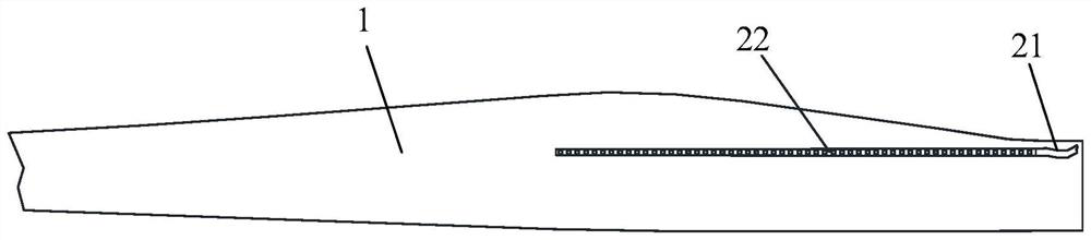
[0045] like figure 1 , Figure 5 and Figure 7 As shown, the blade boundary layer flow control system of this embodiment includes a first guide section 21 and a second guide section 22 . Wherein, the first guide section 21 communicates with the blade cavity 17 . like figure 1 and Figure 4 As shown, the second guide section 22 communicates with the first guide section 21, and the sec...

Embodiment 2

[0061] like Figure 8 and Figure 9 As shown, the second guide section 22 is provided on the side of the suction surface 13 close to the blade trailing edge 12 in this embodiment, and the vortex generator 6 is provided on the side of the suction surface 13 close to the blade leading edge 11 . The vortex generator 6 disposed near the leading edge 11 of the blade can further improve the aerodynamic performance of the fan blade 1 .

[0062] In this embodiment, the length of the second guide section 22 on the side near the trailing edge 12 of the blade is consistent with the length of the vortex generator 6 on the side near the leading edge 11 . Other structures in this embodiment are the same as those in Embodiment 1, so details are not repeated here.

Embodiment 3

[0064] like Figure 10 and Figure 11 As shown, in this embodiment, the side of the suction surface 13 close to the trailing edge 12 of the blade is provided with a second guide section 22 , and the side of the suction surface 13 close to the blade leading edge 11 is also provided with a second guide section 22 . The second guide section 22 disposed near the leading edge 11 of the blade can further improve the aerodynamic performance of the fan blade 1 .

[0065] In this embodiment, the length of the second guide section 22 on the side near the trailing edge 12 of the blade is consistent with the length of the second guide section 22 on the side near the leading edge 11 . Other structures in this embodiment are the same as those in Embodiment 1, so details are not repeated here.


PUM


Abstract

The invention discloses a blade boundary layer flow control system and a wind power generating set including the same. The blade boundary layer flow control system includes: a fan blade, which is an elastic body and has a suction surface, a pressure surface, a blade front edge and a blade rear Edge, wherein, the inside of the fan blade is formed with a blade cavity; the first guide section, the first guide section communicates with the blade cavity; the second guide section, the second guide section communicates with the first guide section, And the second guide section is arranged on the side of the suction surface close to the trailing edge of the blade, and the second guide section has guide air holes. The present invention does not use additional air pumps, air extractors and other airflow generating equipment, and does not consume additional energy, and only uses the air flow generated by the elastic deformation of the fan blade itself during the operation of the wind turbine to control the flow of the blade boundary layer to achieve Inhibit the separation of the boundary layer of the blade, delay the stall of the fan blade, improve the aerodynamic performance of the fan blade, and increase the power generation of the wind turbine.

Description

technical field [0001] The invention relates to a blade boundary layer flow control system and a wind power generating set comprising the same. Background technique [0002] When the wind turbine is running, if the angle of attack of the blade is too large, the blade will have boundary layer flow separation phenomenon, which is called blade stall. The flow separation will cause the lift force of the blade to drop rapidly and the resistance to rise rapidly, resulting in the decline of the aerodynamic performance of the blade and the power generation capacity. The loss was serious. With the increasing size of wind power blades, the requirements for the blade structure are getting higher and higher, and the airfoil with large thickness and blunt trailing edge has become the first choice for the airfoil at the root end of the blade. During the operation of wind turbines, the boundary layer flow separation in the root region of the large-thickness airfoil is prone to occur, and ...

Claims


Application Information

Patent Timeline
Patent Type & Authority Patents(China)
IPC IPC(8): F03D7/02F03D1/06F03D9/25
CPCF03D1/065F03D1/0675F03D7/022F03D9/25Y02E10/72
Inventor 赵越金孝龙
Owner SHANGHAI ELECTRIC WIND POWER GRP CO LTD
Why Eureka
Try Eureka