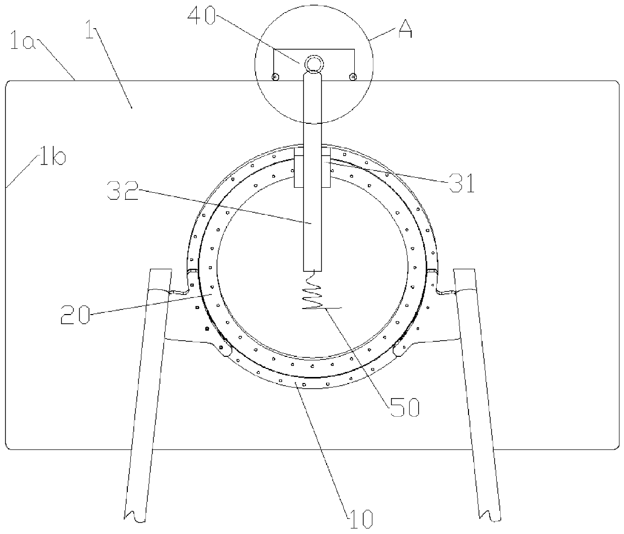
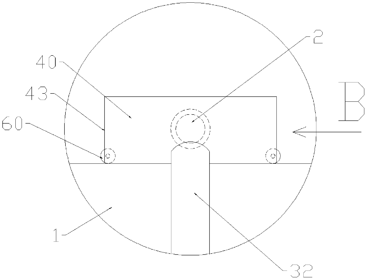
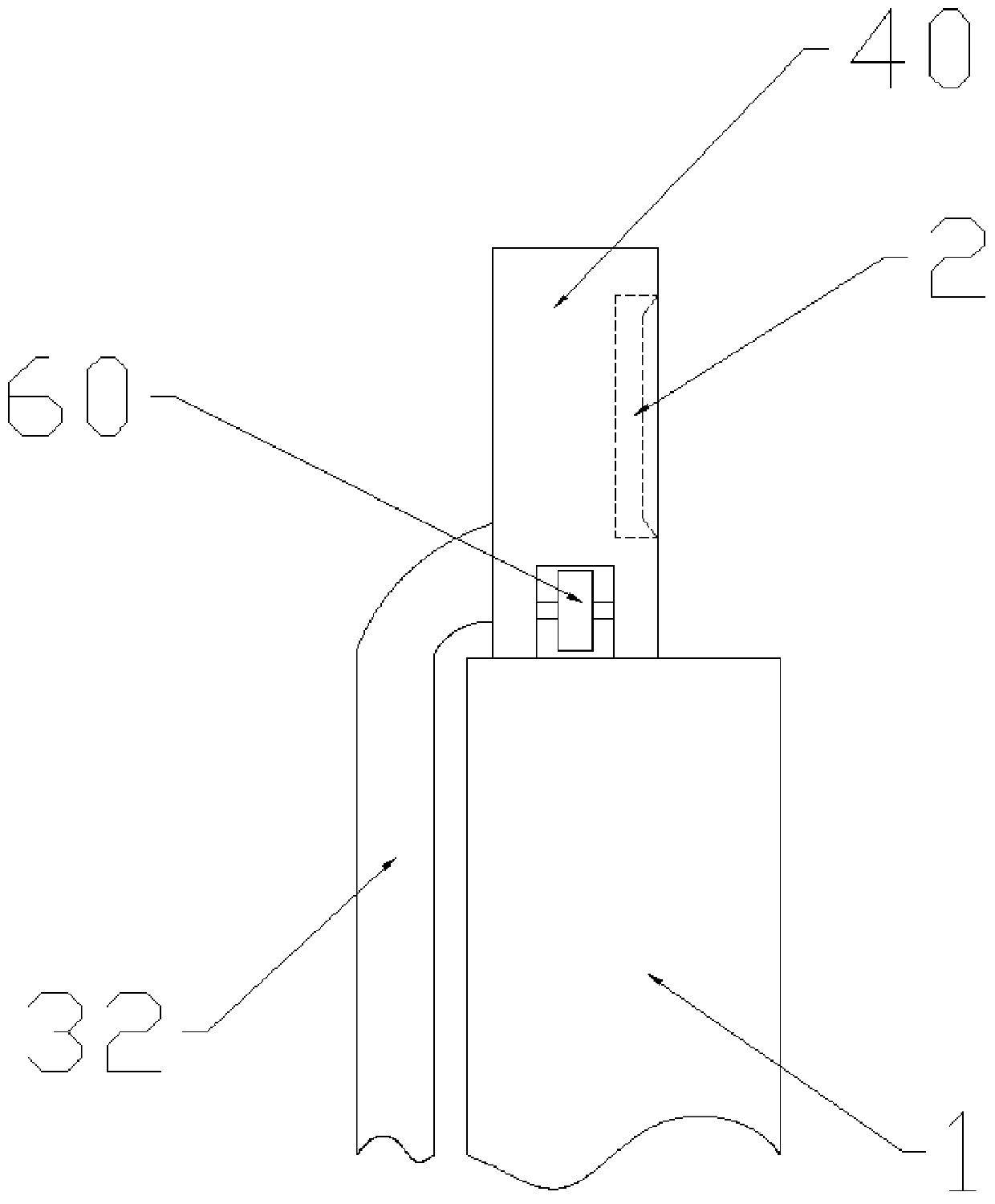
Lifting linkage structure of rotation screen camera

A camera and linkage technology, which is applied in the field of swing screen camera lifting linkage structure, can solve the problems of automatic camera linkage adjustment, poor operation experience, mismatch, etc., and achieve the effect of beautiful and elegant appearance, simple structure and simple structure

Pending Publication Date: 2019-12-20
TAIZHOU STRONKIN ELECTRONICS
View PDF0 Cites 2 Cited by
  • Summary
  • Abstract
  • Description
  • Claims
  • Application Information

AI Technical Summary

Problems solved by technology

[0004] 2) Or the camera is adjusted by manual plugging and unplugging. Before the monitor swings, the camera needs to be removed, and then installed after the swing is in place. It is very inconvenient. The camera cannot be adjusted automatically with the swing of the monitor. The uninterrupted basic video recording process cannot be guaranteed, and the operating experience is very poor
[0005] 3) Part of the camera on the swing bracket can be linked, but it needs to rely on an extremely complicated mechanism to realize the lifting, and the camera cannot always fit the display frame. During the adjustment process, it needs to be separated from the display frame, which looks very mismatched and affects the perception.

Method used


Image

  • Lifting linkage structure of rotation screen camera
  • Lifting linkage structure of rotation screen camera
  • Lifting linkage structure of rotation screen camera

Examples


Embodiment Construction

[0056] The technical solutions of the present invention will be clearly and completely described below in conjunction with the accompanying drawings. Apparently, the described embodiments are some of the embodiments of the present invention, but not all of them. Based on the embodiments of the present invention, all other embodiments obtained by persons of ordinary skill in the art without making creative efforts belong to the protection scope of the present invention.

[0057] In the description of the present invention, it should be noted that the terms "center", "upper", "lower", "left", "right", "vertical", "horizontal", "inner", "outer" etc. The indicated orientation or positional relationship is based on the orientation or positional relationship shown in the drawings, and is only for the convenience of describing the present invention and simplifying the description, rather than indicating or implying that the referred device or element must have a specific orientation, ...


PUM


Abstract

The invention provides a lifting linkage structure of a rotation screen camera. The lifting linkage structure comprises a bracket, a screen rotation connection base, a fixed rail, a moving rail and acamera mounting base; the camera mounting base and the moving rail are arranged in a T shape as a whole; the lower portions of the left side and the right side of the camera mounting base are each provided with a rolling element; the rolling elements protrude from the side surfaces of the camera mounting base; and a sliding working surface is arranged at the position, between the two rolling elements, at the bottom of the camera mounting base. Through the extremely simple structure, highly difficult trajectory motion, expected by users, of the camera which can always move along the edge of a display in an attached mode when the display and the screen rotation connection base are rotated is achieved. During the rotation process of the display, the camera does not leave a frame of the display and is not turned along with the display, the appearance is quite attractive and elegant, and the motion trajectory, expected by the users, of the camera is achieved.

Description

technical field [0001] The invention relates to the technical field of displays, in particular to a lifting and lowering linkage structure of a swing screen camera. Background technique [0002] The swing bracket of the existing large display has the following technical problems during the swing process of the display: [0003] 1) The camera is fixedly installed on the display and rotates along with the screen, causing the video recording process to be interrupted or flipped into chaos; [0004] 2) Or the camera is adjusted by manual plugging and unplugging. Before the monitor swings, the camera needs to be removed, and then installed after the swing is in place. It is very inconvenient. The camera cannot be adjusted automatically with the swing of the monitor. There is no guarantee that the basic video recording process will be uninterrupted, and the operating experience is very poor. [0005] 3) Part of the camera on the swing bracket can be linked, but it needs to rely ...

Claims


Application Information

Patent Timeline
Patent Type & Authority Applications(China)
IPC IPC(8): F16M11/06F16M11/20G09F9/00G03B17/56
CPCF16M11/06F16M11/20G09F9/00G03B17/56
Inventor 曲波
Owner TAIZHOU STRONKIN ELECTRONICS
Why Eureka
Try Eureka